PCC-IV Instruction Manual (rev. 0.2)
Page 5-9
Section 5 – Configuring Blockware
Modifying the Front Panel Settings
The PANEL function block is used in Blockware by the
programmer to control alarm enable, silence, and output
signals. See Section 6 for more details.
To change Front Panel Settings, click on the
Edit
tab on the
Tool Bar and then click on
Open Panel Settings
on the
Ribbon. This will open the Panel Data Screen where the
programmer can set up everything related to the Front Panel. This is usually performed after the programmer is
finished setting up the rest of the Blockware so that Tags, Push Buttons, and LEDs are already set up.
•
Display Channel – There are up to 10 Display Channels that the user scrolls through by pressing the DIS
soft-button. The programmer sets those up here. Set the following for each Display Channel:
o
Click the cell in the Source Tag column and select the appropriate Tag from the dropdown list.
o
Enter the number of digits to be displayed to the right of the decimal point.
o
Enter the Zero and Span values to be displayed, but without the decimal point.
Example: 0.00-100.00% Block Output corresponds to -12.0” to +12.0” Drum Level.
Enter: Decimal Point = 1, Zero = -120, Span = +120, Message = DRUM LEVEL.
The Span can be less than the Zero (e.g..: Zero = +120 and Span = -120).
o
Enter the message to show in the message display (i.e. Steam PSI or Drum Level).
•
Alarm Channel – You can set up to 10 alarms which will show on the Front Panel Alarm Annunciator and
cause the PANEL Block to output a Common Alarm signal. See Section 6 for more information. Set the
following for each Alarm Channel:
o
Click the cell in the Source Tag column and select the appropriate Tag from the dropdown list.
These can be any digital Tag or Alarm Tag.
o
Enter the message to be displayed on the Front Panel Alarm Annunciator Screen.
•
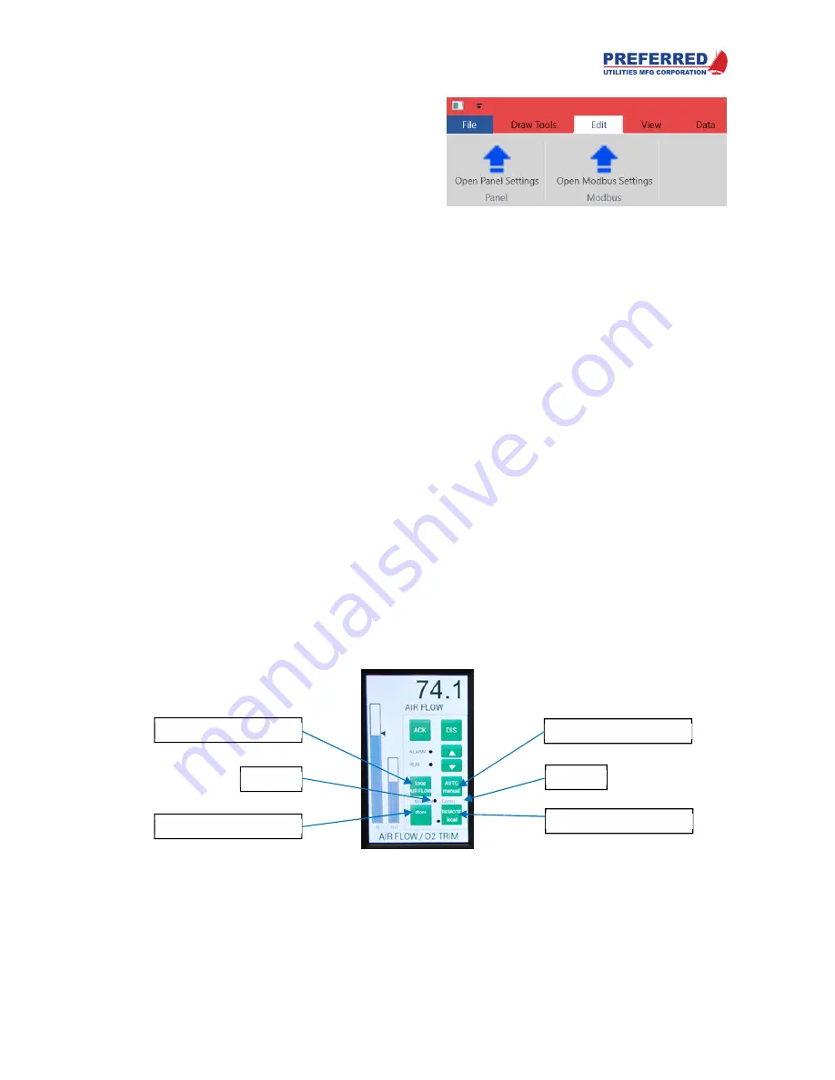
Push Button – There are up to 4 user-configurable pushbuttons that are set up here. The buttons are
arranged from left-to-right, top-to-bottom (1 = top-left, 2 = top-right, 3 = bottom-left, 4 = bottom right). Set
the following for each Push Button:
o
Click the cell in the Source Tag column and select the appropriate Tag from the dropdown list.
These can be any digital Tag or Alarm Tag, but the tag must be connected to a PB (pushbutton)
block.
o
Type specifies how the PB will respond to a press. “MOM_HI” or momentary high means the
output = 1 for as long as the button is pressed. “MOM_LO” or momentary low means the
output = 0 for as long as the button is pressed. “TOGGLE” means the output changes to the
opposite of the previous output during the first scan of every button press.
o
There are two lines of text available on each button. The programmer can change these lines of
text depending on whether the output = 1 or 0. Upper Message On = the top line when the output
is a 1. Lower Message On = the lower line when the output is a 1. Likewise, the programmer
would enter text for the Upper and Lower messages when the output is a 0.
•
LED Number – there are up to 6 user-configurable LEDs that are set up here. The LEDs next to each
pushbutton are numbered the same as the pushbuttons (1-4). LEDs 5 & 6 are the two between the upper
and lower pushbuttons. Set the following for each LED:
o
Click the cell in the Source Tag column and select the appropriate Tag from the dropdown list.
These can be any digital Tag or Alarm Tag.
o
Enter the text to be displayed next to the LED (LEDs 5 & 6).
•
Loop Names – These specify the text that will be displayed at the bottom of the operator screen depending
on which control loop is selected. This ensures the operator knows which control function is currently being
Pushbutton 2 & LED 2
Pushbutton 4 & LED 4
Pushbutton 1 & LED 1
Pushbutton 3 & LED 3
LED 5
LED 6
Содержание PCC-IV
Страница 3: ...PCC IV Instruction Manual rev 0 2 Page iii ...
Страница 4: ...PCC IV Instruction Manual rev 0 2 Page iv ...
Страница 5: ...PCC IV Instruction Manual rev 0 2 Page v ...
Страница 6: ...PCC IV Instruction Manual rev 0 2 Page vi ...
Страница 70: ...PCC IV Instruction Manual rev 0 2 Page 5 3 Section 5 Configuring Blockware PCC IV Blocks Figure 5 1 ...


