background image

6.

Set the display back in its mounting position and reconnect the data cable.Set the on/off 
switch in the “on” position. 

7.

If the display is unresponsive immediately when the EFX is powered up, replace the upper 
PCA.

8.

If the display is operating normally when the EFX is powered up, replace the display housing 
front panel. The display housing front panel is equipped with the keypad.

9.

If you have performed all of the procedures above and have been unable to correct the 
problem, call Precor customer service.

10. Access the service mode program per Procedure 2.1.

11. Test the keypad per the Key Test Procedure. 

12. If all of the keys test good, the problem may be user error or a key function that is normally 

disabled during a particular user program. 

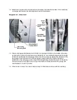
13. If one or more keys do not function correctly, either the keypad (display housing) or upper 

PCA could be defective. Replace the display and repeat step 11. If the display housing did 
not correct the problem, re-install the original display housing and replace the upper PCA.

14. If you have performed all of the procedures above and have been unable to correct the 

problem, call Precor customer service.

Содержание EFX EFX 5.23

Страница 1: ...roduct This document contains general product information software diagnostic procedures when available preventative maintenance procedures inspection and adjustment procedures troubleshooting procedu...

Страница 2: ...from ears and neck tie up long hair remove neck ties and do not wear loose clothing Exercise caution when touching any wire or electrical component during EFX operation Caution statements are intende...

Страница 3: ...itch away from water and other liquids Do not use accessory attachments that are not recommended by the manufacturer such attachments might cause injuries General Information For the latest exploded v...

Страница 4: ...ENT phillips and flat head screwdrivers digital multimeter standard and metric allen wrench sets open end wrench set Supplies blue loctite drive ratchet and ratchet set socket drive allen set cable ti...

Страница 5: ...ests Upper and Lower Software Versions Key Test Factory Set Display Test Procedure 1 Plug the power cord into the wall outlet then turn on the EFX with the on off switch 2 While pressing and holding t...

Страница 6: ...ry set clears user parameters and returns all programs to the factory default settings 9 If do you do not wish to restore the factory settings use the S T keys to move to the display test or key test...

Страница 7: ...ile pressing and holding the ENTER key press the RESET INCLINE S and RESISTANCE T keys sequentially 3 The upper display screen will scroll the upper and lower software versions 4 The lower display scr...

Страница 8: ...1 Plug the power cord into the wall outlet then turn on the EFX with the on off switch 2 While pressing and holding the ENTER key press the RESET INCLINE T and RESISTANCE S keys sequentially 3 UNIT CH...

Страница 9: ...ion check mode The incline is now in the correct position to be calibrated If incline calibration is required see Procedure 5 3 Incline calibration is typically only required after the incline motor h...

Страница 10: ...errors are present in the error log NO ERROR will scroll across the lower display 5 If errors are present they will scroll across the lower display in the form 1 ERROR XX AT XXX STRIDES XX HOURS 6 Us...

Страница 11: ...rsion numbers for upper and lower PCA s Note Look at the PROM mounted on the upper PCA A label on the PROM indicates the software version number The part number of the PROM indicates the version numbe...

Страница 12: ...eels and frame with a damp cloth Every Week Wipe the surface of the electronic console with a slightly damp sponge or soft cloth Dry with a clean towel CAUTION Keep water away from electronic componen...

Страница 13: ...c display does not change appropriately troubleshoot per section 6 4 6 Press the RESISTANCE S key until you reach Resistance Level 8 Operate the EFX for another 2 3 minutes 7 If the EFX resistance doe...

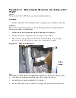
Страница 14: ...rs as described in Procedure 7 1 2 Set the ohmmeter to a range that will conveniently read up to 125 3 Disconnect the J1 magnet connector from the lower PCA Measure the resistance between the two term...

Страница 15: ...locking tabs If necessary use pliers to bend the locking tabs out of the way so that the bolts can be turned 6 If the step up pulley belt is out of alignment to the right continue with step 8 7 If the...

Страница 16: ...auge Slide one of the o rings up against the shoulder of the belt gauge Press downward on the belt gauge causing the belt to deflect Read the deflection on the belt gauge at the edge of the straight e...

Страница 17: ...nment is still correct by performing the procedure in step 4 17 When both the step pulley belt tension and alignment are correct use pliers to bend the tension bolt locking tabs into the locking posit...

Страница 18: ...ght While maintaining constant pressure on pulley check the belt tension with your finger When the belt tension feels correct tighten and torque the input belt tension bolt to 200 inch pounds 17 foot...

Страница 19: ...Support the ramp If the ramp is not supported it will fall during the next step 6 Remove both yoke mounting bolts Slide the lift motor out of the yoke 7 Insert the A C line cord in the A C outlet set...

Страница 20: ...th the bolts removed in step 6 13 Place the top retaining bracket in its mounting position and fasten it with the screws removed in step 4 14 Set the front portion of the front cover in its mounting p...

Страница 21: ...to the twelve o clock position and measure the distance from the crankarm to the frame weldment See Diagram 5 6 Rotate the opposite crankarm to the twelve o clock position and measure the distance fr...

Страница 22: ...ow block mounting bolts to 120 inch pounds 10 foot pounds Input Drive Axle to Step Up Pulley Axle Alignment 8 Mark the current position of the step up pulley on both side of the drive weldment 9 On bo...

Страница 23: ...tive to the eddy current disk The eddy current disk should be centered in the slot in the eddy current magnet See Diagram 5 9 Diagram 5 9 Eddy Current Magnet 16 If the eddy current disk is not centere...

Страница 24: ...cables or the mid point connector Continue with step 8 8 Carefully remove the right side outrigger see Procedure 7 22 The mid point connector is in the lower front opening of the right side outrigger...

Страница 25: ...ay is unresponsive immediately when the EFX is powered up continue with the next step 3 This condition may be caused by either the keypad or upper PCA Set the on off switch in the off position Remove...

Страница 26: ...blem call Precor customer service 10 Access the service mode program per Procedure 2 1 11 Test the keypad per the Key Test Procedure 12 If all of the keys test good the problem may be user error or a...

Страница 27: ...view the Warning and Caution statements listed in Section One Things You Should Know Procedure 1 Remove the upper and right rear cover sections per Procedure 7 1 Set the on off switch in the on positi...

Страница 28: ...per Procedure 7 12 Skip to step 8 5 With the an ohmmeter connected to terminals 2 and 6 of J7 on the lower PCA rock the step up disk forward and backward so that the magnet is passing in front of and...

Страница 29: ...ge across the magnet wires at the lower PCA J1 1 J1 2 The voltage should measure approximately 25 Vdc If the voltage is missing or significantly low continue with step 3 3 Set the on off switch in the...

Страница 30: ...ime If the new part does not correct the problem re install the original part 9 Set the on off switch in the off position Using an ohmmeter measure between the magnet wires at the lower PCA The measur...

Страница 31: ...necessary 9 If the reading in step 5 is significantly low replace the lower PCA 10 If you have performed all of the above tests and are unable to resolve the problem contact Precor customer support 11...

Страница 32: ...bove tests and are unable to resolve the problem contact Precor customer support Diagram 6 3 Lower PCA J1 Magnet J3 AC Neutral J2 AC Hot J7 Speed Sensor J4 Lift Drive J5 Lift Position J6 Data Cable TP...

Страница 33: ...ions that are bad If the cable and connectors are good continue with step 5 5 Set the on off switch in the off position Remove the F1 lift fuse 2 amp slow blow fuse from the lower PCA Measure the fuse...

Страница 34: ...CLINE key is pressed the problem is either the upper PCA or the keyboard display housing Troubleshoot the keyboard per the keyboard portion of Procedure 2 1 If the keyboard is good replace the upper P...

Страница 35: ...that you are replacing Rear Cover Removal Right Hand Cover Section 3 Remove the two screws from the right front upper and right front lower corners of the right hand cover section 4 Remove the right...

Страница 36: ...n its mounting position 17 Fasten the bottom cover section with the screws removed in step 14 18 Set the A C input module in its mounting position and fasten it with the screws removed in step 13 19 P...

Страница 37: ...center portion and the rear outside portion of the top cover with the screws removed in step 7 Left Cover Section 25 Set the left hand cover section in its mounting position and fasten it with the scr...

Страница 38: ...and heart rate cable from the rear of the display assembly 5 Remove the eight screws that fasten the display assembly s rear cover to the display assembly 6 Remove the four screws that fasten the uppe...

Страница 39: ...ap on cover from the lower PCA 5 Disconnect the magnet cable J1 the speed sensor cable J7 the lift drive cable J4 the lift position cable J5 the data cable J6 green yellow ground wire and A C cables J...

Страница 40: ...lower data cable is routed through the frame from the bottom of the right outrigger tube to the lower PCA 1 Set the on off switch in the off position then unplug the power cord from the A C outlet Re...

Страница 41: ...start but do not tighten the four lower and three upper right out rigger mounting bolts removed in steps 5 and 6 Tighten these seven bolts after all have been hand started 13 Place the ferrite removed...

Страница 42: ...ng the two data cables and discard the old data cable 27 Connect the new data cable to the connector module and to the lower PCA 28 Slide the right outrigger into its mounting position 29 Hand start b...

Страница 43: ...y Module 3 Remove the blue wire from terminal D the brown wire from terminal A and the green wire from the ground terminal of the power entry module 4 Remove the two screws that fasten the power entry...

Страница 44: ...the wires removed in step 3 Connect the blue wire to terminal D the brown wire to terminal A and the green wire to the ground terminal of the power entry module 9 Replace the left and right hand cover...

Страница 45: ...You Should Know 2 Remove the left and right hand cover sections as described in Procedure 7 1 3 Remove the left and or right stairarm assembly as described in Procedure 7 17 Note Notice the position o...

Страница 46: ...8 Replace the stairarm assembly as described in Procedure 7 17 9 If you are replacing both crankarm assemblies repeat steps 6 7 and 8 for the second crankarm assembly 10 Set the unit at it s highest...

Страница 47: ...belt See Diagram 5 3 b Straighten the locking tabs and turn the left and right tension bolts counterclockwise until tension is removed from the step up belt See Diagram 5 3 c Slide the input and step...

Страница 48: ...6 Diagram 7 5 Pillow Block Bearings 13 Replace the stairarms per Procedure 7 17 14 Check drive input adjustment per Procedure 5 4 15 Replace the top left and right cover sections per Procedure 7 1 Mo...

Страница 49: ...uld Know 2 Remove the top left and right cover sections as described in Procedure 7 1 3 Remove the stairarm assemblies as described in Procedure 7 17 4 Remove the crankarm assemblies as described in P...

Страница 50: ...arting with the bottom left hand bolt then the bottom right hand bolt the upper right hand bolt and then the upper left hand bolt 9 Tighten the right and left hand step up belt tension bolts and the i...

Страница 51: ...escribed in Procedure 7 17 4 Remove the crankarm assemblies as described in Procedure 7 6 5 Mark the current position of the step up belt tension bolts and the position of the idler pulley mounting bo...

Страница 52: ...op and the stamping on one pillow block bearing on the bottom See Diagram 7 5 13 Thread and hand tighten the pillow block mounting bolts into the drive weldment upright Torque the pillow block mountin...

Страница 53: ...r in this procedure See Diagram 5 3 6 Remove tension from the drive belts and remove the pillow block bearings per Procedure 7 7 7 Remove the input drive assembly from the unit per Procedure 7 8 8 Rem...

Страница 54: ...lt to the settings marked in step 5 15 Verify the tension of the belts per Procedure 5 2 16 Replace the crankarm s per Procedure 7 6 17 Replace the stairarms per Procedure 7 17 18 Check drive input ad...

Страница 55: ...sting tension settings later in this procedure See Diagram 5 4 4 Remove tension from the drive belts 5 Slide the step up and input belts off of their pulleys 6 Remove the left and right tension bolts...

Страница 56: ...lower PCA 4 Disconnect the speed sensor cable from the J7 connector on the lower PCA See Diagram 6 3 5 Unsnap the speed sensor from the speed sensor bracket and remove the speed sensor See Diagram 7 7...

Страница 57: ...the bolts that secure the magnet assembly to the drive unit Remove the magnet from the drive unit 5 Position the replacement magnet assembly at its mounting position so that the eddy current disk is...

Страница 58: ...cribed in Procedure 7 1 3 If the moveable arm s connecting link is attached to the stairarm remove it from the stairarm and attach it to its storage point on the frame 4 Remove the mounting bolt and n...

Страница 59: ...red spacer is on the top and the black spacer is on the bottom of the pivot block as shown in Diagram 7 9 Install and hand tighten the stairarm pivot block mounting hardware The mounting bolt head mu...

Страница 60: ...nts listed in Section One Things You Should Know 2 Remove the left and right cover sections as described in Procedure 7 1 3 Remove the stairarm pivot block retaining ring flat washer and wave washer f...

Страница 61: ...amp channel from the rear of the ramp Slide the stairarm pivot block onto the crankarm pin and replace the wave washer flat washer and retaining ring removed in step 3 8 Replace the left and right cov...

Страница 62: ...off position then unplug the power cord from the wall outlet WARNING Before continuing with this procedure review the Warning and Caution statements listed in Section One Things You Should Know 2 Remo...

Страница 63: ...sections as required as described in Procedure 7 1 3 5 25 only Remove the bolt that fasten the stairarm link to the stairarm See Diagram 7 12 Diagram 7 12 5 25 Stairarm Link 4 Remove the mounting bolt...

Страница 64: ...Install and hand tighten the stairarm pivot block mounting hardware The mounting bolt head must be on the top of the stairarm as shown in Diagram 7 9 Torque the stairarm pivot block mounting bolt to 1...

Страница 65: ...with this procedure review the Warning and Caution statements listed in Section One Things You Should Know 2 Set the on off switch in the off position then unplug the power cord from the wall outlet 3...

Страница 66: ...e upper end of the ramp to the lift motor yoke with the hardware removed in step 6 Torque the two lower ramp bolts to 480 inch pounds 40 foot pounds Diagram 7 14 Upper Ramp Mounting Viewed from under...

Страница 67: ...e wall outlet WARNING Before continuing with this procedure review the Warning and Caution statements listed in Section One Things You Should Know 2 Remove the bolt and nut that fastens the forward en...

Страница 68: ...ts mounting position Carefully hand start the moveable handlebar s mounting bolt to avoid cross threading and then tighten 6 Set the connecting link in its mounting at the lower end of the moveable ha...

Страница 69: ...ibed in Procedure 7 1 3 Mark the current position of the idler pulley mounting bolt in its adjustment slot with a pen or white out This will enable you to recreate the existing tension setting later i...

Страница 70: ...and both yoke mounting bolts from the lift nut Diagram 7 18 Ramp Mounting 8 Remove the two screws in the bottom rear portion of the cover 9 Swing the lift motor forward and slide the cover section off...

Страница 71: ...ken because the upper data cable is inside of the right outrigger 5 Remove the three screws from the rear of the display assembly that fasten it to the upright support If you are removing the left out...

Страница 72: ...upport 14 Remove the foot from the outrigger and install it on the replacement outrigger See Diagram 7 20 Diagram 7 20 Outrigger Foot 15 Hand start but do not tighten the four lower and three upper ou...

Страница 73: ...unting bracket is removed The support will also facilitate the mounting and alignment of the replacement ramp mounting bracket 4 Remove the four screws that fasten the ramp mounting bracket to the ram...

Страница 74: ...the power entry module 4 The fuse module contains two fuses carefully remove one or both fuses out of the fuse module as required 5 Insert the replacement fuse s into the fuse module Use only 2 amp t...

Страница 75: ...ng bolts from the lift nut Remove the rear incline cover section Diagram 7 23 Ramp Mounting 6 Disconnect the lift motor cable connector and remove the lift motor frame ground 7 Remove the bolt that fa...

Страница 76: ...r incline cover section in its mounting position Move the lift motor into place with the lift nut in between the tines of the yoke Fasten the lift nut to the yoke with yoke mounting bolts removed in s...

Страница 77: ...e illustration below 4 The IC s may inserted into their socket by hand by carefully aligning the notch on the IC with the notch on the IC socket and carefully pressing the IC into its socket See the i...

Страница 78: ...G Y JK1 JK2 JK5 2 5 8 JK5 1 4 7 JK5 6 JK5 3 Mid Point Connector Mid Point Connector JK6 2 5 8 JK6 1 4 7 JK6 3 JK6 6 AC Hot AC Neutral BR BL BK BK J7 2 J7 6 G Y R BK J1 2 J1 1 J4 1 J4 2 J4 3 J5 1 J5 3...

Страница 79: ...Block Diagram 8 2 5 23 5 25...

Отзывы: