21
PM-1440BV v3 2020-10
Copyright © 2020 Quality Machine Tools, LLC
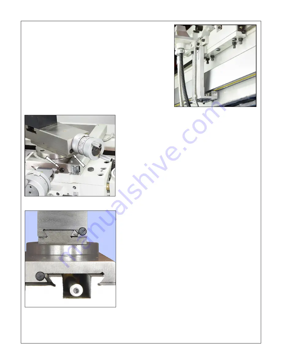
GIB ADJUSTMENT
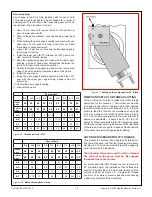
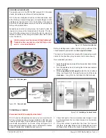
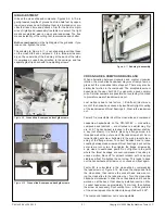
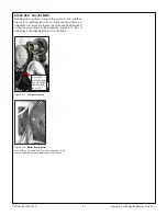
Gibs on the cross slide and compound, Figures 4-9, 4-10, are
gently-tapered lengths of ground cast iron held fast by oppos-
ing screws at each end. Adjusting them is a trial and error pro-
cess that takes time and patience. Aim for the best compro-
mise of rigidity and reasonably free table movement. Too tight
means accelerated wear on ways and leadscrews. Too free
means instability of the cutting tool, inaccuracies and chatter.
Both screw heads
must be tight against the gib ends. If you
loosen one, tighten the other.
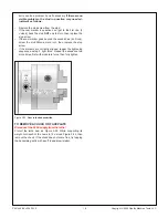
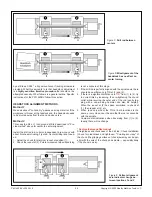
The saddle gib, Figure 4-11, is not a tapered insert like those
on the cross slide and compound. It is a three-part assem-
bly on the underside of the bed way at the back of the lathe.
It comprises a support bar, attached to the carriage, and two
separate gib strips each with two adjusting screws.
Figure 4-9
Cross slide & compound front gib screws
Figure 4-10
Cross slide & compound back gib screws
Figure 4-11
Saddle gib assembly
CROSS-SLIDE & COMPOUND BACKLASH
When alternating between clockwise and counter clockwise
rotation, the cross-slide handwheel may move freely a few de-
grees but the cross-slide table stays put. There may also be
similar lost motion in the compound. The acceptable amount
depends on the user, but 0.005” is generally a good compro-
mise. Smaller numbers are possible, but overdoing it can lead
to premature wear of leadscrew and nut.
Lost motion is due to two factors: 1. End-float (in/out move
-
ment of the handwheel) caused by insufficiently tight coupling
of the leadscrew and thrust bearings. 2. Wear in the leadscrew
nut.
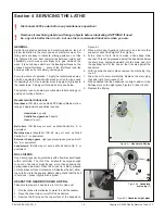
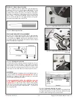
Factor #1 is correctable in both the cross-slide and compound.
Leadscrew handwheels on the PM-1440BV — cross-slide,
compound and tailstock — are attached in a similar way, Fig-
ure 4-13. The handwheel is locked to the leadscrew shaft by
a key (not shown). It is held in place by a flange screw in a
threaded well at the outer end of the leadscrew shaft. An in-
ternal locking set screw, bottomed in the well, prevents loos-
ening of the flange screw. To correct backlash due to loose
coupling between leadscrew and thrust bearings, back out the
set screw a turn or two, then tighten the flange screw using
a pin vise or needle-nose pliers. Do not tighten to the point
where the thrust bearings are over-compressed, resulting in
uneven motion. Back off for smooth rotation, with no appre
-
ciable end-float. Re-tighten the set screw. This tends to back
out the handwheel a small amount, so check end-float again.
Factor #2 is correctable in the cross-slide by compressing
the leadscrew nut, Figure 4-14. Remove the compound from
the cross-slide, then remove the socket head screw secur-
ing the cross-slide to the leadscrew nut. Turn the cross-slide
handwheel clockwise to drive the nut backward until it can be
worked on at the back. If not already installed, insert an M6 x
1 socket head screw, approximately 15 mm long, then tighten
the screw as necessary. Don't overdo this — a 45 degree turn
of the screw represents a backlash take-up of about 0.005".
The compound leadscrew nut is not adjustable.


