Precision matthews PM-1022V Скачать руководство пользователя страница 17

17

PM-1030V v5 2020-10

Copyright © 2020 Quality Machine Tools, LLC

COMPOUND SETUP FOR THREAD CUTTING

Thread cutting on the lathe is unlike most other turning oper-

ations, for two reasons: 1. The cutting tool must be precisely 

ground with an included angle of 60 degrees for most Amer-

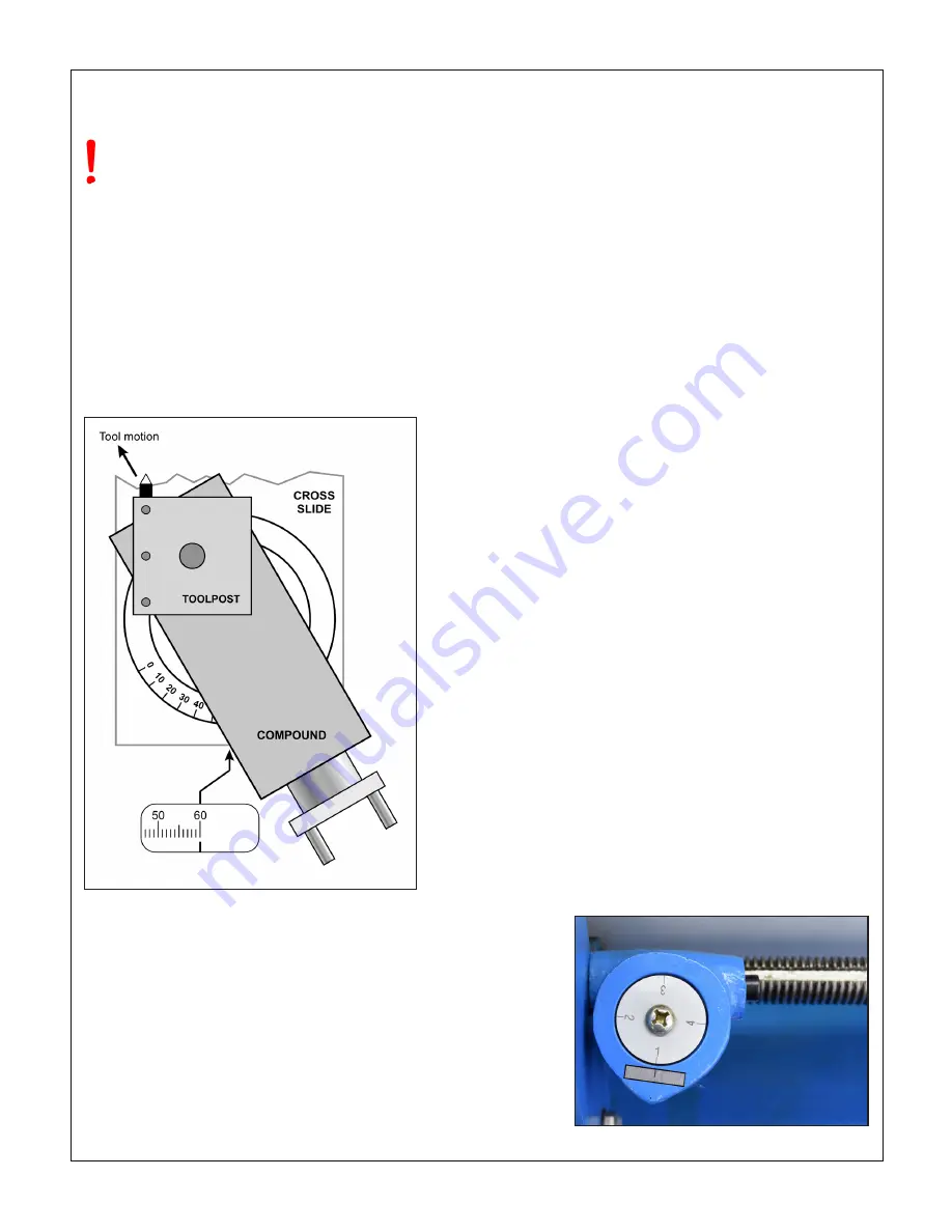
ican and metric threads, and; 2. It is preferable to feed the 

tool into the workpiece at an angle so it cuts mostly on the left 

flank of the thread, Figure 3-18. The correct angle relative to 

the cross-slide (zero degrees) is debatable — should it be 29, 

29-1/2 or 30 degrees? Many machinists prefer 29 degrees be-

cause it holds the cutting tool marginally clear of the right flank 

of the thread, close enough for cleanup of the flank while at the 

same time avoiding appreciable rubbing.

Figure 3-23  

Setting the compound for 30

o

 infeed

THREAD CUTTING

A key fact to remember ...

For metric threads the half-nut in the apron must 

remain engaged throughout the entire process.

CUTTING PROCEDURE FOR TPI THREADS

This procedure assumes that a single point thread cutting tool 

will be used, and that the worm wheel on the threading dial 

assembly properly engages the leadscrew, Figure 3-x.

The  threading  dial  cannot  used  for  metric  threads!  The 

split-nut on the apron must not be disengaged until the 

threading operation is completed.

For metric and UNC/UNF threads the tool is ground to 60

o

 (in-

cluded angle). It is installed so that its flanks are exactly 30

o


either side of the cross axis, ideally with the compound offset 

as Figure 3-23. Single-point threads are cut in as many as 

10 successive passes, sometimes more, each shaving a little 

more material off the workpiece.

To make the first thread-cutting pass the leadscrew is run at 

the selected setting (tables on following two pages), and the 

saddle is moved by hand to set the cutting tool at the start-

ing point of the thread. With the tool just grazing the work-

piece, the half-nut lever (Figure 3-19) is lowered to engage 

the leadscrew. This can be done at any point, 

provided

 the 

split-nut remains engaged throughout the 

entire multi-pass 

thread cutting process

.

When the first pass is completed, the tool is backed out clear 

the workpiece (using the cross-slide), and the spindle is re-

versed to bring the saddle back to the starting point. The cross-

slide is returned to its former setting, then the tool is advanced 

a few thousandths by the compound for the next pass. Each 

successive pass is done in the same way, each with a slightly 

increased infeed setting of the compound.    

Many users working on U.S. threads save time by disengaging 

the split-nut at the end of each cutting pass, reversing the sad-

dle quickly by hand, then re-engaging, usually by reference to 

the threading dial, Figure 3-24.

For most TPI numbers every engagement, 

including the first

must at the point where a 

specific


line

 on the threading dial 

comes into alignment with the datum mark. If not, the second 

and subsequent passes will be out of sync. In some cases, 

see the “visualization” Figure 3-26, there is a choice of lines for 

re-engagement, but in every case the process calls for careful 

timing.

[NOTE:  Disengagement  and  re-engagement  of  the  split-

nut is not applicable to metric threads — leave the split-

nut engaged throughout the entire process]

Typical depths of cut per pass vary from an initial 0.005” or so, 

to as little as 0.001”, even less. A finishing pass or two with 

increments of only 0.0005” — or none at all, to deal with the 

spring-back effect, can make all the difference between a too-

tight thread and one that runs perfectly.

Assuming that the compound is set over at between 29 and 

30 degrees, the total depth of cut is approximately 0.69 times 

the thread pitch, P (this equates to a straight-in thread depth of 

0.6 times P). There may be a need for a few thousandths more 

in-feed than 0.69P, almost certainly not less. 

Figure 3-25  

Threading dial (US threads only)

Содержание PM-1022V

Страница 1: ... jaw and 4 jaw chucks Faceplate steady follower rests Quick change tool post tool holders Gearbox and change gears for full range screw cutting U S TPI Metric Bi directional power feed for saddle cross slide Weight excluding stand approx 395 360 lb Models PM 1022V PM 1030V This manual was written for the Model PM 1030V The PM 1022V is identical in all respects other than overall weight and bed dim...

Страница 2: ...V machines as shipped from late 2017 There may be detail differences be tween your specific machine and the information given here with little or no impact on functionality Please email us if you have questions about any aspect of the manual or your machine see our website www preci sionmatthews com for support addresses Your feedback is welcomed This material was originated by Precision Matthews ...

Страница 3: ...m cover at left also access to the electrical box at the back of the headstock Power requirement is 110V 60Hz single phase Extension cord not recommended if no alternative use 12 AWG not longer than 20 ft Before connecting power be sure that 1 The machine is on a firm footing 2 Chuck attachment bolts are tight no wrench left in chuck 3 Saddle and cross slide approx mid travel power feed disengaged...

Страница 4: ...ake sure all leveling mounts and or shims are properly weight bearing firmly in contact with the floor Check and ad just level from end to end using a precision machinist s level When selecting a location for the lathe allow sufficient room at the right to allow removal servicing of the leadscrew Be sure to keep all lifting gear clear of any part of the lathe especially the leadscrew at the front ...

Страница 5: ...imes 1 With the power feed and half nut levers in neutral run the ALIGNING THE LATHE The most important attribute of a properly set up lathe is its ability to machine parallel to cut a cylinder of uniform diame ter over its entire length In other words no taper Leveling of the lathe is a part of this see earlier in this section Equally important is the alignment of the center to center axis with t...

Страница 6: ...ndle has a 1 inch bore and is unusually short just 11 inches ideal for through spindle work Long service life is assured by high precision taper roller spindle bearings together with hardened and ground bed ways All internal gears in the gearbox and apron are continuously splash lubricated Power feed for the saddle and cross slide is supplied by a three speed gearbox driving a two in one leadscrew...

Страница 7: ...can be hazardous Be sure the work area is properly lit Never leave chuck keys wrenches or other loose tools on the machine Be sure the workpiece toolholder s and machine ways are secure before commencing operations Use moderation light cuts low spindle speeds and slow table motion give better safer results than hogging Don t try to stop a moving spindle by hand allow it to stop on its own Disconne...

Страница 8: ...lide travel 3 in Drive system DC drive with 2 speed Vee pulleys Low range rpm 50 to 1000 High range rpm 100 to 2000 Saddle drive thread cutting Leadscrew 8 TPI 3 4 in diameter Inch threads Choice of 37 from 8 to 80 TPI Metric threads Choice of 21 from 0 35 mm to 3 mm pitch Saddle cross slide drive turning facing Worm driven by keyed slot in leadscrew Turning operations saddle feed Choice of feed r...

Страница 9: ... engine lathes that require little explanation except for specific details speed control thread cutting and the saddle cross slide pow er feed system Because the user is assumed to be familiar with general purpose metal lathes this section contains very little tutorial Those unfamiliar with lathe work may find the following helpful HOW TO RUN A LATHE published many years ago by the original South ...

Страница 10: ...surface of the headstock Figure 3 4 Figure 3 4 Spindle speed sensor CHUCK REMOVAL REPLACEMENT Chucks and faceplates are secured to the PM 1030V spin dle by three threaded studs and nuts Figures 3 7 and 3 8 A knurled shutter ring allows the chuck to be removed or re in stalled with the nuts in place more convenient than if the nuts would need to be reattached in the small gap between spindle nose a...

Страница 11: ... of 0 001 On the cross slide dial only this shows as 0 002 per division meaning that a 0 001 depth of cut reduces the diameter of the workpiece by 0 002 The compound can be rotated through 360 degrees It rests on a turntable casting with a 60 degree graduated scale Figure 3 11 The compound is secured to the cross slide by a clamp ring and two M8 T screws with lock nuts Figures 3 12 and 3 13 SADDLE...

Страница 12: ...g Figure 3 14 QCTP with toolholder This style of toolholder is used for rectangular shank tools up to 1 2 x 1 2 Its height is set by the thumb nut resting on the top surface of the toolpost The wave washer and hex locknut prevent accidental rotation of the thumb nut To rotate the QCTP loosen the center post Offset screw Figure 3 15 Tailstock The safety screw prevents accidental dropping of the tai...

Страница 13: ...d between centers and indicated along its length Figure 3 17 lists the coarse and fine feed rates available with two external gear setups Because the difference between the two is quite small 1 4 1 many users opt for one or the other for all their work saving time by not changing external gears The gearbox A B C provides 2 1 and 4 1 speed choices with in each range External change gear swapping Th...

Страница 14: ...slide feed Lever LEFT and DOWN Engage by first shifting the power feed lever to the right or left then swing the lever up or down Disengage by swinging the lever to its mid position Figure 3 19 Figure 3 19 Power feed disengaged POWER FEED Thread cutting operations For thread cutting the saddle is driven by the threads on the leadscrew in combination with a half nut in the apron Figure 3 19 Before ...

Страница 15: ...gear 76T 75T 60T 80T 80T 80T B 9 1 2 11 1 2 15 16 A 19 23 30 32 36 40 C 38 46 60 64 72 80 Less common threads not illustrated Z3 40T 50T 55T 65T B 8 10 11 13 A 16 20 22 26 C 32 40 44 52 Z3 varies see table below B 9 A 18 C 36 B 12 A 24 C 48 B 14 A 28 C 56 THREAD CUTTING SETUPS U S threads in TPI threads per inch Figure 3 21 Gear setups for U S threads ...

Страница 16: ...0T C 0 35 0 40 0 45 0 50 A 0 70 0 80 0 90 1 00 B 1 40 1 60 1 80 2 00 Not illustrated Z2 65T Z3 45T Z4 39T Lower gear 63T C A 1 75 B THREAD CUTTING SETUPS Metric threads in mm pitch C A 1 25 B 2 50 C 0 75 A 1 50 B 3 00 C 0 60 A 1 20 B 2 40 Figure 3 22 Gear setups for metric threads ...

Страница 17: ...oint of the thread With the tool just grazing the work piece the half nut lever Figure 3 19 is lowered to engage the leadscrew This can be done at any point provided the split nut remains engaged throughout the entire multi pass thread cutting process When the first pass is completed the tool is backed out clear the workpiece using the cross slide and the spindle is re versed to bring the saddle b...

Страница 18: ... the half nut on any line also mid way be tween the numbered lines on the dial marking the mid points will give you double the number of re engagement choices Special cases if the 2 result is an even whole number ex ample 12 2 6 there are even more re engagement choices see the visualization chart above This may not be usable in practice due to the difficulty of estimating the exact point to re en...

Страница 19: ...e step by step procedure for setting up the steady rest de pends on personal preferences Some users start by fixing the steady rest casting on the bed then mounting the workpiece in a chuck or between centers others set up the workpiece first then install the steady rest on the lathe bed Either way the region of the workpiece under the steady rest fingers must run true and the fingers must not app...

Страница 20: ...y oil such as Mobil Vactra No 2 or equivalent Machine ways dovetails ISO 68 way oil such as Mobil Vactra No 2 or equivalent External change gears light general purpose grease NLGI No 2 or equivalent Leadscrews ISO 68 way oil such as Mobil Vactra No 2 or equivalent BALL OILERS Use a pump type oil can preferably with a flexible spout tipped with a soft tube The ID of the tip should be large enough t...

Страница 21: ...ow the oil to drain completely then replace the drain plug 5 Using a funnel and tubing assembly as described above for the gearbox add an ounce or two of oil 6 When satisfied that the gearbox is oil tight add oil to the halfway mark on the sight glass about 1 pint 7 Replace the fill plug Figure 4 3 Apron fill plug sight glass LUBRICATION OILERS Figure 4 4 Saddle cross slide oilers Figure 4 5 Compo...

Страница 22: ...addle gib support The saddle gib is not adjustable Figure 4 12 Spindle nut Figure 4 10 Compound gib screws three Arrowed screw is the lock screw ADJUSTMENT CROSS SLIDE BACKLASH When alternating between clockwise and counter clockwise rotation the cross slide handwheel may move freely a few de grees but the cross slide table stays put Cross slide lost motion is due to two factors 1 Too loose at tac...

Страница 23: ...when the cross slide is moved inward In this diagram the pointer is shown turning clockwise 8 Pre load the indicator by a few thousandths then traverse the saddle from 1 to 2 If the pointer turns clockwise as you go toward the tailstock as Figure C the tailstock is biased to the front This will cause the lathe to cut a tapered workpiece with the larger diameter at the headstock end Correct this by...

Страница 24: ... Z1051 7 Nut M10 Z1052 8 Double ended stud M10 x 115 Z1053 9 Washer Φ10 Z1054 10 Screw M10 x 20 Z1055 11 Sleeve Z1056 12 Gear 40T Z1057 13 Spindle pulley Z1058 14 V belt 7M730 Z1006 Ref Description Part 15 Locknut Z1060 16 Screw M5 x 10 Z1061 17 Support plate Z1062 18 Double ended stud M10 x 115 Z1063 19 Motor mount Z1064 20 Washer Φ6 Z1065 21 Screw M6 x 10 Z1066 22 Set screw M6 x 10 Z1067 23 Moto...

Страница 25: ... This is typically a one time adjustment thereafter the axle can be treated as a one piece shoulder bolt Dimensions in millimeters Ref Description Part 1 Oiler Φ6 Z1074 3 Gear axle Z1075 4 Special C washer Z1076 5 Ext keyed bushing Z1077 8 Thin spacer washer special Z1078 9 T nut Z1079 13 Skt hd cap screw M6 x 10 Z1080 14 Special C washer Z1081 15 Int keyed bushing Z1082 19 Change gear support bar...

Страница 26: ...26 PM 1030V v5 2020 10 Copyright 2020 Quality Machine Tools LLC GEARBOX Fig 3 There may be detail differences between this representative drawing and the machine as supplied ...

Страница 27: ...20 End plug Z1105 21 Triple gear assembly Z1106 22 Gear shifter crank Z1107 23 Pin Φ5x16 Z1108 24 Shifter fork Z1109 25 Hex set screw M6 x 6 Z1110 26 Shifter fork Z1111 Ref Description Part 27 Screw M6 x 45 Z1112 28 Bushing Z1113 29 Shaft Z1114 30 Circlip Z1115 31 Intermediate gear Z1116 32 End plug Z1117 33 Sliding bearing 1610 Z1118 34 Circlip Z1119 35 Gear Z1120 36 Key Z1121 37 Shaft Z1122 38 K...

Страница 28: ...28 PM 1030V v5 2020 10 Copyright 2020 Quality Machine Tools LLC APRON Fig 4 There may be detail differences between this representative drawing and the machine as supplied ...

Страница 29: ...2 Z1167 31 Worm gear 17T Z1000 32 Int keyed worm Z1169 33 Key 4 x 4 x 12 Z1170 34 Worm gear shaft Z1171 35 Set screw coned M4 x 8 Z1172 36 Collar Z1173 Ref Description Part 37 Roll pin Φ4 x 20 Z1174 38 Gear 34T Z1175 39 Cam shaft Z1176 40 Pin 8 x 24 Z1177 41 Half nut Z1178 42 Half nut support Z1179 43 Screw M5 x 30 Z1180 44 Set screw coned M4 x 8 Z1181 45 Roll pin Φ4 x 20 Z1182 46 Bushing Z1183 47...

Страница 30: ...020 10 Copyright 2020 Quality Machine Tools LLC SADDLE CROSS SLIDE Fig 5A There may be detail differences between this representative drawing and the machine as supplied Leadscrew drive gear not shown in above drawing ...

Страница 31: ...de block Z1266 58 Saddle clamp block Z1267 59 Saddle gib support Z1268 60 Screw M4 x 20 Z1269 61 Saddle gib Z1270 62 Screw M3 x 8 Z1271 63 V wiper backing front Z1272 64 Rubber V wiper front Z1273 65 Plain wiper backing rear Z1274 66 Plain wiper rear Z1275 67 Cover Z1276 68 Screw M4 x 8 Z1277 69 Compound swivel base Z1278 70 Locknut M4 Z1279 Ref Description Part 1 Toolpost handle Z1210 2 Handle hu...

Страница 32: ...32 PM 1030V v5 2020 10 Copyright 2020 Quality Machine Tools LLC BED TAILSTOCK Fig 6 There may be detail differences between this representative drawing and the machine as supplied ...

Страница 33: ...Nut M10 Z1302 25 Washer Φ10 Z1303 26 Set screw M6 x 10 Z1304 27 Adjusting block Z1005 28 Screw M6 x 16 Z1306 29 Clamp bolt Z1307 30 Screw M8 x 25 Z1308 Ref Description Part 31 Tailstock base Z1309 32 Offset label Z1310 33 Screw M8 x 30 Z1311 34 Screw M5 x 8 Z1312 35 Splash guard Z1313 36 Clamp plate Z1314 37 Threaded stud M12 M10 Z1315 38 Spring 13 x 1 x 62 Z1316 39 Washer Φ12 Z1317 40 Nut M12 Z13...

Страница 34: ...x 6 Z1339 3 Nut M4 Z1340 4 Front panel Z1341 5 Forward reverse switch Z1342 6 Speed display Z1343 7 Screw M4 x 14 Z1344 8 E Stop switch Z1345 9 Screw M3 x 6 Z1346 10 Upper panel Z1347 11 Potentiometer Z1348 Ref Description Part 12 Electrical box Z1349 13 Filter unit Z1350 14 Screw M4 x 14 Z1351 15 Nut M4 Z1352 16 Motor control unit Z1043 17 Rear cover Z1354 18 Screw M4 x 12 Z1355 19 Fuse holder Z1...

Страница 35: ...tacts RUN MOTOR STOP MOTOR E Stop Chuck Guard and Gear Cover CHANGING MOTOR DIRECTION When rotated from F to R and vice versa the Direction Switch swaps the A and A connections to the motor switch contacts 1 and 7 to 2 and 6 HOW THE CONTACTOR WORKS If and only if the Direction Switch F O R is set to either F or R the neutral N line is connected to the normally open RUN MOTOR contact The hot line L...

Страница 36: ...36 PM 1030V v5 2020 10 Copyright 2020 Quality Machine Tools LLC Filter unit Motor control unit There may be detail differences between this representative drawing and the machine as supplied ...

Отзывы: