background image

10

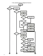
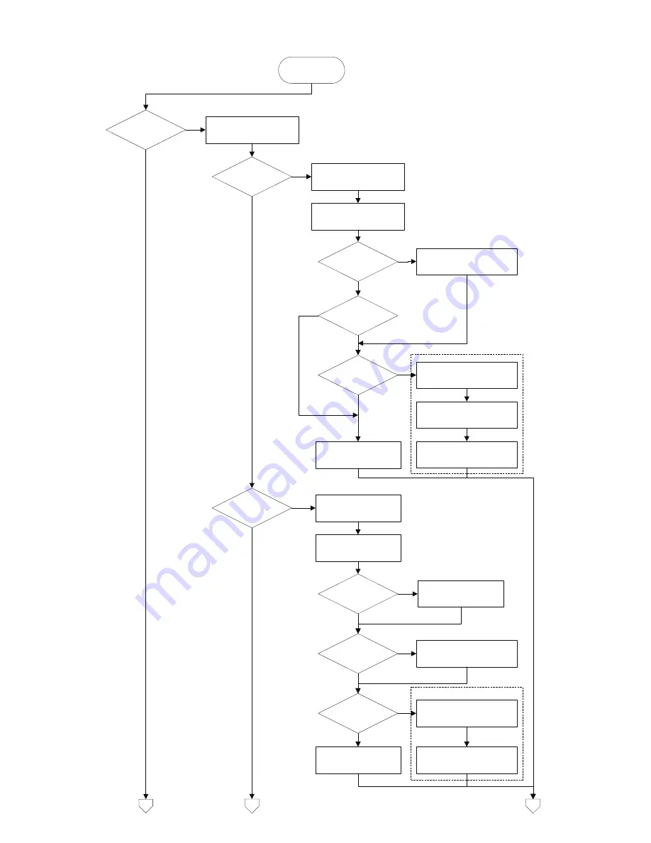
2.5 AI_Transducer Block Configuration Flowchart

Configure 5350 

Transducer block

Temperature 

measurement?

Set

PRIMARY_VALUE_UNIT

to F,R,C or K

RTD?

Thermo-couple?

Set LIN_TYPE to RTD 

type (Pt100 etc.)

4-wire?

Set

SENSOR_CONNECTION 

to 2-,3- or 4-wire. 

Enter wire resistance in 

Ohms for both wires to 

COMP_WIRE1

2-wire?

Enter wire resistance in 

Ohms for both wires to 

COMP_WIRE2

YES

Enter setup for sensor 2:

YES

Set LIN_TYPE to TC 

type (TC K etc.)

Set RJ_TYPE (internal, 

external etc.) 

Set LIN_TYPE_2 to RTD 

type (Pt100 etc.)

Set

SENSOR_MEAS_TYPE 

to single sensor type

Dual sensor?

Enter setup for sensor 2:

Set LIN_TYPE_2 to TC type 

(TC K etc.)

Enter RJ temperature to 

EXTERNAL_RJ_VALUE

RJ_TYPE 

external?

YES

YES

RJ_TYPE

ext. 2.wire?

Enter wire resistance in 

Ohms for both wires to 

COMP_WIRE_RJ

YES

YES

YES

2c

Set

SENSOR_MEAS_TYPE 

to single sensor type

2b

2a

Set SENSOR_MEAS_TYPE 

to dual sensor type

Set SENSOR_MEAS_TYPE 

to dual sensor type

YES

Dual sensor?

YES

Содержание 5350

Страница 1: ...5 3 5 0 PROFIBUS PA FOUNDA TION Fieldbus Transmitter N o 5 3 5 0 Q 1 0 2 0 4 2 0 F r o m s e r n o 0 3 0 6 4 0 0 0 1 Approvals Configuration Manual FOUNDA TION Fieldbus ...

Страница 2: ...ple with two sensors 14 2 6 5 Measurement of combined sensors Sensor 1 TC and Sensor 2 RTD 14 2 6 6 Measurement of resistance linear with one sensor 14 2 6 7 Measurement of resistance linear with two sensors 15 2 6 8 Measurement of potentiometer linear with one sensor 15 2 6 9 Measurement of potentiometer linear with two sensors 15 2 6 10 Measurement of voltage linear with one sensor 16 2 6 11 Mea...

Страница 3: ...Supported Modes 29 3 6 To enable the Simulation mode 29 3 7 Alarm Types 29 3 8 Mode Handling 29 3 9 Status Handling 29 3 10 Initialisation 29 3 11 Analogue Input Blocks Parameter List Fieldbus Foundation 29 4 0 PID Control Block Fieldbus Foundation 31 4 1 Introduction 31 4 2 Overview 31 4 3 Schematic 31 4 4 Description 31 4 5 Supported Modes 32 4 6 Alarm Types 32 4 7 Mode Handling 32 4 8 Status Ha...

Страница 4: ... are xxyy ffo Device Description binary file xxyy sym Device Description symbol file xxyyzz cff Capability file xx yy and zz refer to the version numbers of the files PR electronics fieldbus transmitters are delivered with a CD that contains the files needed to configure the transmitters from a fieldbus host These files can also be downloaded from our homepage www prelectronics com Please follow t...

Страница 5: ...lable the result will be a block alarm for a configuration error The RS_STATE parameter contains the operational state of the Function Block Application for the resource containing this resource block 1 3 RESTART parameter The RESTART parameter allows degrees of initialization of the resource They are 1 Run it is the passive state of the parameter 2 Restart resource it is intended to clear up prob...

Страница 6: ...t and cleared by writing to the WRITE_LOCK parameter Clearing WRITE_LOCK will generate the discrete alert WRITE_ALM at the WRITE_PRI priority Setting WRITE_LOCK will clear the alert if it exists Be fore setting WRITE_LOCK parameter to Locked it is necessary to select the Soft Write lock supported option in FEATURE_SEL 1 10 Features being implemented The parameter CYCLE_TYPE is a bit string that de...

Страница 7: ... locate the DD file for the resource Un signed 8 SRC 1 RO 1 GRANT_DENY 14 Access Permissions Options for controlling access of host com puter and local control panels to operating tuning and alarm parameters of the block DS 70 SRC 2 R W 0 HARD_TYPES 15 The types of hardware available as channel numbers BIT_ STRING SRC 2 RO 0 RESTART 16 1 Run 2 Restart resource 3 Restart with defaults 4 Restart pro...

Страница 8: ...E_EVT 35 This alert is generated by any change to the static data DS 73 D 14 RO 0 0 0 0 0 9 0 BLOCK_ALM 36 The block alarm is used for all configuration hardware connec tion failure or system problems in the block The cause of the alert is entered in the sub code field The first alert to become active will set the Active status in the Status attribute As soon as the Unreported status is cleared by...

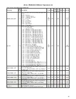
Страница 9: ...oduct specific parameters are set off in grey background in the TB Parameter List In order to configure these parameters the files mentioned in the introduction must be available to the application software 2 3 Default configuration PR electronics delivers the transmitters with at default configuration which will suit the cus tomer s demand in many cases The configuration task has thus been reduce...

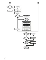
Страница 10: ...E2 YES Enter setup for sensor 2 YES Set LIN_TYPE to TC type TC K etc Set RJ_TYPE internal external etc Set LIN_TYPE_2 to RTD type Pt100 etc Set SENSOR_MEAS_TYPE to single sensor type Dual sensor Enter setup for sensor 2 Set LIN_TYPE_2 to TC type TC K etc Enter RJ temperature to EXTERNAL_RJ_VALUE RJ_TYPE external YES YES RJ_TYPE ext 2 wire Enter wire resistance in Ohms for both wires to COMP_WIRE_R...

Страница 11: ...IRE1 2 wire YES Enter setup for sensor 2 YES Set LIN_TYPE_2 to no linearisation or linearisation table Set SENSOR_MEAS_TYPE to single sensor type Set LIN_TYPE to no linearisation or linearisation table Set SENSOR_MEAS_TYPE to dual sensor type Enter wire resistance in Ohms for both wires to COMP_WIRE2 Millivolts Set PRIMARY_VALUE_UNIT to V mV or µV Set LIN_TYPE to no linearisation or linearisation ...

Страница 12: ...ion table Set SENSOR_MEAS_TYPE to single sensor type Set LIN_TYPE to no linearisation or linearisation table Set SENSOR_MEAS_TYPE to dual sensor type Enter wire resistance in Ohms for 2 wires to COMP_WIRE2 Error try again Finished Transducer block is configured Enter Custom RTD polynomial values Linearisation table Custom RTD Enter linearisation table values YES YES Enter Custom TC polynomial valu...

Страница 13: ...R_MEAS_TYPE Anything but not PV SV_1 SV_2 not available SENSOR_CONNECTION 2 or 3 wire SENSOR_CONNECTION_2 Default set to 2 wire RJ_TYPE N A ignored in setup check Connections 2 6 3 Measurement of thermocouple with one sensor PRIMARY_VALUE_UNIT K C F or R LIN_TYPE Any TC LIN_TYPE_2 N A ignored in setup check SENSOR_MEAS_TYPE PV SV_1 SV_2 not available SENSOR_CONNECTION N A ignored in setup check SE...

Страница 14: ... but not PV SV_1 SV_2 not available SENSOR_CONNECTION N A ignored in setup check SENSOR_CONNECTION_2 2 or 3 wire RJ_TYPE No Reference Junction Internal External constant value Connections 2 6 6 Measurement of resistance linear with one sensor PRIMARY_VALUE_UNIT Ohm or kOhm LIN_TYPE No linearisation LIN_TYPE_2 N A ignored in setup check SENSOR_MEAS_TYPE PV SV_1 SV_2 not available SENSOR_CONNECTION ...

Страница 15: ...S_TYPE PV SV_1 SV_2 not available SENSOR_CONNECTION 3 or 4 wire SENSOR_CONNECTION_2 N A ignored in setup check RJ_TYPE N A ignored in setup check Connections 2 6 9 Measurement of potentiometer linear with two sensors PRIMARY_VALUE_UNIT LIN_TYPE No linearisation LIN_TYPE_2 No linearisation SENSOR_MEAS_TYPE Anything but not PV SV_1 SV_2 not available SENSOR_CONNECTION Default set to 3 wire SENSOR_CO...

Страница 16: ... PRIMARY_VALUE_UNIT LIN_TYPE Table Linearisation LIN_TYPE_2 Table Linearisation same table as sensor 1 SENSOR_MEAS_TYPE Anything but not PV SV_1 SV_2 not available SENSOR_CONNECTION Default set to 3 wire SENSOR_CONNECTION_2 Default set to 3 wire RJ_TYPE N A ignored in setup check Connections The coordinates x y describing the linear interpolation linearisation must be entered in PR_ CUST_LIN Block...

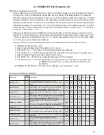
Страница 17: ...POLY_COUNT 5 CUSTOM_TC_MIN_IN 6500 0 CUSTOM_TC_MIN_OUT 100 0 CUSTOM_TC_MAX_OUT 1200 0 A TC input of 5000 µV and an RJ temperature of 25ºC will make POLY_3 the active and the out put will be URJ 3 94 10 1 3 94 101 25 2 65 10 2 252 1 11 10 4 253 1000 µV This voltage is to be added to the TC voltage 5000 1000 and the resulting temperature will be 4 18 2 26 10 2 6000 1 41 10 7 60002 1 50 10 11 60003 1...

Страница 18: ... SENSOR_CONNECTION_1 2 COMP_WIRE_1 2 Process calibration Min Max hold min max min max MIN_SENSOR_VALUE_1 2 MAX_SENSOR_VALUE_1 2 RTDX_FACTOR_1 2 CAL_POINT_HI_1 2 CAL_ACTUAL_HI_1 2 CABLE_RES1 2 RJ RJ_COMP_WIRE SENSOR_WIRE_CHECK_1 2 SENSOR_WIRE_CHECK_RJ CUSTOM_TC_ TAB_X_Y_VALUE CUSTOM_RTD_ Channel_4 Channel_1 Channel_2 Channel_3 AI_TRANSDUCER and PR_CUST_LIN schematic CAL_POINT_LO_1 2 CAL_ACTUAL_LO_1...

Страница 19: ...Ni IEC 584 133 TC Type J Fe Cu45Ni IEC 584 134 TC Type K Ni10Cr Ni5 IEC 584 135 TC Type N Ni14CrSi NiSi IEC 584 136 TC Type R Pt13Rh Pt IEC 584 137 TC Type S Pt10Rh Pt IEC 584 138 TC Type T Cu Cu45Ni IEC 584 139 TC Type L Fe CuNi DIN 43710 140 TC Type U Cu CuNi DIN 43710 240 Custom defined TC 241 Custom defined RTD 242 Custom defined RTD PtX a 0 003850 X factor of Pt1 243 Custom defined RTD NiX a ...

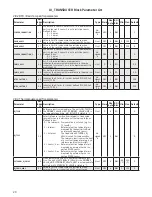
Страница 20: ..._2 66 Indicates the X factor for custom defined PtX NiX CuX for LIN_TYPE_2 Un signed 16 SRC 2 R W 100 2 8 3 Thermocouple specific parameters Parameter Rel Index FF Description Type Store Size byte RO R W Min Max Default RJ_TEMP 32 Reference junction temperature The unit of RJ_TEMP is the PRIMARY_VALUE_UNIT If PRIMARY_VALUE_UNIT is no temperature unit e g mV RJ_TEMP is stated in C Float D 4 RO 0 RJ...

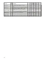
Страница 21: ... R W 0 MAX_SENSOR_VALUE_1 28 Holds the maximum SECONDARY_VALUE_1 The unit is defined in SECONDARY_VALUE_1 Float N 4 R W 0 MIN_SENSOR_VALUE_1 29 Holds the minimum SECONDARY_VALUE_1 The unit is defined in SECONDARY_VALUE_1 Float N 4 R W 0 MAX_SENSOR_VALUE_2 30 See MAX_SENSOR_VALUE_1 Float N 4 R W 0 MIN_SENSOR_VALUE_2 31 See MIN_SENSOR_VALUE_1 Float N 4 R W 0 2 8 5 Output parameters Parameter Rel Ind...

Страница 22: ...ERROR 62 Diagnostic bit value indicating hardware status 0 hardware OK Bit 0 Input power supply error 1 Input initialisation error 2 Input communication error 3 Internal temperature sensor error 4 Device not factory calibrated 5 6 reserved 7 Watchdog initiated cold start occurred Un signed 8 D 1 RO 0 2 8 7 Sensor error detection parameters Parameter Rel Index FF Description Type Store Size byte RO...

Страница 23: ...nt of the deviation starts by typing in a random value and PR5350 calculates the curve slope according to the measured deviations 8 SENSOR_CAL_METHOD_1 104 the sensor calibration just carried out is used 2 8 9 Sensor Calibration Parameters Parameter Rel Index FF Description Type Store Size byte RO R W Min Max Default CAL_POINT_LO_1 46 The low calibration value applied to sensor 1 The value from ei...

Страница 24: ... applied CAL_POINT_HI_2 value Float SRC 4 R W 1038 SENSOR_CAL_METHOD_2 58 Enables or disables the last sensor calibration for sensor 2 103 Factory trim standard calibration values disabled 104 User trim standard calibration values enabled Un signed 8 SRC 1 R W 103 SENSOR_CAL_LOC_2 59 The last location of the calibrated sensor OCTET_ STRING SRC 32 R W SENSOR_CAL_DATE_2 60 The last date on which the...

Страница 25: ...earisation x y coordinate 2 Float array SRC 8 R W 1000 100 TAB_X_Y_VALUE3 39 Linearisation x y coordinate 3 Float array SRC 8 R W 2000 200 TAB_X_Y_VALUE4 40 Linearisation x y coordinate 4 Float array SRC 8 R W 3000 300 TAB_X_Y_VALUE5 41 Linearisation x y coordinate 5 Float array SRC 8 R W 4000 400 TAB_X_Y_VALUE6 42 Linearisation x y coordinate 6 Float array SRC 8 R W 5000 500 TAB_X_Y_VALUE7 43 Lin...

Страница 26: ... x y coordinate 42 Float array SRC 8 R W 0 0 TAB_X_Y_VALUE43 79 Linearisation x y coordinate 43 Float array SRC 8 R W 0 0 TAB_X_Y_VALUE44 80 Linearisation x y coordinate 44 Float array SRC 8 R W 0 0 TAB_X_Y_VALUE45 81 Linearisation x y coordinate 45 Float array SRC 8 R W 0 0 TAB_X_Y_VALUE46 82 Linearisation x y coordinate 46 Float array SRC 8 R W 0 0 TAB_X_Y_VALUE47 83 Linearisation x y coordinate...

Страница 27: ... converting µV to C Consisting of maximum input value in µV a4 a0 polynomial coefficients 6 Float SRC 24 R W 120000 0 0 0 0 01 0 CUSTOM_TC_POLY_5 22 Polynomial part 5 of Custom defined TC converting µV to C Consisting of maximum input value in µV a4 a0 polynomial coefficients 6 Float SRC 24 R W 150000 0 0 0 0 01 0 CUSTOM_TC_RJ_POLY 23 RJ Polynomial part of custom defined TC converting C to µV a3 a...

Страница 28: ...h the channel units code if one exists or the block will remain in O S mode after being configured A block alarm for units mismatch will be generated The OUT_SCALE is normally the same as the transducer but if L_TYPE is set to Indirect or Ind Sqr Root OUT_SCALE determines the conversion from FIELD_VAL to the output PV and OUT always have identical scaling OUT_SCALE provides scaling for PV The PV i...

Страница 29: ...on is required This is a pure calculation algorithm 3 11 Analogue Input Blocks Parameter List Fieldbus Foundation Parameter Rel Index Description Type Store Size byte RO R W Min Max Default ST_REV 1 The revision level of the static data associated with the function block To support tracking changes in static parameter attributes the associated block s static revision parameter will be incre mented...

Страница 30: ... 18 Time constant of a single exponential filter for the PV in sec onds Float SRC 4 R W 0 FIELD_VAL 19 Raw value of the field device in percent of thePV range with a status reflecting the Transducer condition before signal charac terization L_TYPE or filtering PV_FTIME DS 65 D 5 RO UPDATE_EVT 20 This alert is generated by any change to the static data DS 73 D 14 RO BLOCK_ALM 21 The block alarm is ...

Страница 31: ...D which is used when the process itself does the integration As long as an error exists the PID function will integrate the error which moves the output in a direction to cor rect the error PID blocks may be cascaded when the difference in process time constants of a primary and secondary process measurement makes it necessary or desirable 4 3 Schematic 4 4 Description The Process Value to be cont...

Страница 32: ...nute The human interface to these parameters should be able to display the user s preference The Direct Acting control option if true causes the output to increase when the PV exceeds the SP If false the output will decrease when the PV exceeds the SP It will make the difference between positive and negative feedback so it must be set properly and never changed while in an automatic mode The setti...

Страница 33: ... 100 GRANT_DENY 12 Options for controlling access of host computer and local control panels to operating tuning and alarm parameters of the block DS 70 SRC 2 R W CONTROL_OPTS 13 Options which the user may select to alter the calculations done in a control block Bit String SRC 2 R W 0 STATUS_OPTS 14 Options which the user may select in the block processing of status Bit String SRC 2 R W 0 IN 15 The...

Страница 34: ...nits code and number of digits to the right of the decimal point associated with TRK_VAL DS 68 SRC 11 R W 0 100 TRK_IN_D 38 This discrete input is used to initiate external tracking of the block output to the value specified by TRK_VAL DS 66 N 2 R W TRK_VAL 39 This input is used as the track value when external tracking is enabled by TRK_IN_D DS 65 N 5 R W FF_VAL 40 The feed forward value and stat...

Страница 35: ...INF DV_LO_PRI 58 Priority of the low deviation alarm Un signed 8 SRC 1 R W 0 15 0 DV_LO_LIM 59 The setting of the low deviation alarm limit in engineering units Float SRC 4 R W PV span 0 INF HI_HI_ALM 60 The status for high high alarm and its associated time stamp DS 71 D 16 R W HI_ALM 61 The status for high alarm and its associated time stamp DS 71 D 16 R W LO_ALM 62 The status of the low alarm a...

Страница 36: ...distributes a priority driven token to devices between scheduled transmissions Any device on the link may become the LAS as long as it is capable The devices that are ca pable of becoming the LAS are called link master devices All other devices are referred to as basic devices When a segment first starts up or upon failure of the existing LAS the link mas ter devices on the segment bid to become t...

Страница 37: ...m www prelectronics se sales se prelectronics com www prelectronics com sales uk prelectronics com www prelectronics com sales us prelectronics com www prelectronics cn sales cn prelectronics com www prelectronics be sales be prelectronics com Head office Denmark www prelectronics com PR electronics A S sales prelectronics dk Lerbakken 10 tel 45 86 37 26 77 DK 8410 Rønde fax 45 86 37 30 85 ...

Отзывы: