22
User Manual
neuro 200
Figure 10.4
RS485
: Serial Communication Port (Terminals 10, 11)
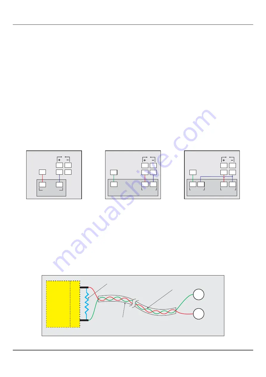
Connect terminal 11 and 10 of the controller to (+) and (-) RS485 terminals of the Master device.
To ensure reliable operation of the Serial Communication Link (without data corruption due to line noise or reflections), use a
pair of twisted wires inside screened cable with the terminating resistor (100 to 150 Ohms) at one end, as shown in Figure 10.4
below.
Terminating Resistor
Screened Cable
Twisted
Wire Pair
(100 to 150 Ohms)
HOST
B-
B+
Master Device
Serial Comm.
Terminals
B-
10
B+
11
mA / V Output
The Positive (+) of mA / V is available at Terminal 14 & the Negative (-) at Terminal 13.
Relay Output
Potential-free Relay changeover contacts NO (Normally Open) and C (Common) rated 10A/240 VAC (resistive load).
SSR Output
Connect (+) and (-) terminals of SSR to (+) and (-) terminals of controller, respectively. Use Zero-Crossover, 3 to 30 VDC
operated SSR.
EXC 5/12/24VDC :
Excitation Voltage for Transmitters (Terminal : 5)
The Controller
30
is supplied with either 5 or 12 or 24VDC @
mA power source. This is primarily meant for exciting 2-wire or 4-
wire Current / Voltage output transmitters. Please note that only the Source terminal (positive) is provided on the back panel
termination. The Sensor negative terminal is used as Return terminal (ground) for excitation output.
2-wire Current Transmitter
(5/12/24VDC Supply)
5
EXC
5/12/24V
-
+
4 to 20mA
Output
16
17
mA
13
14
3-wire Voltage Transmitter
(5/12/24VDC Supply)
+
Supply
1 to 3.6 V
Output
+
5
EXC
5/12/24V
16
17
V
13
14
-
4-wire Voltage Transmitter
(5/12/24VDC Supply)
1 to 3.6 V
Output
+
Supply
5
EXC
5/12/24V
V
16
17
13
14
+
-
-


