background image

30

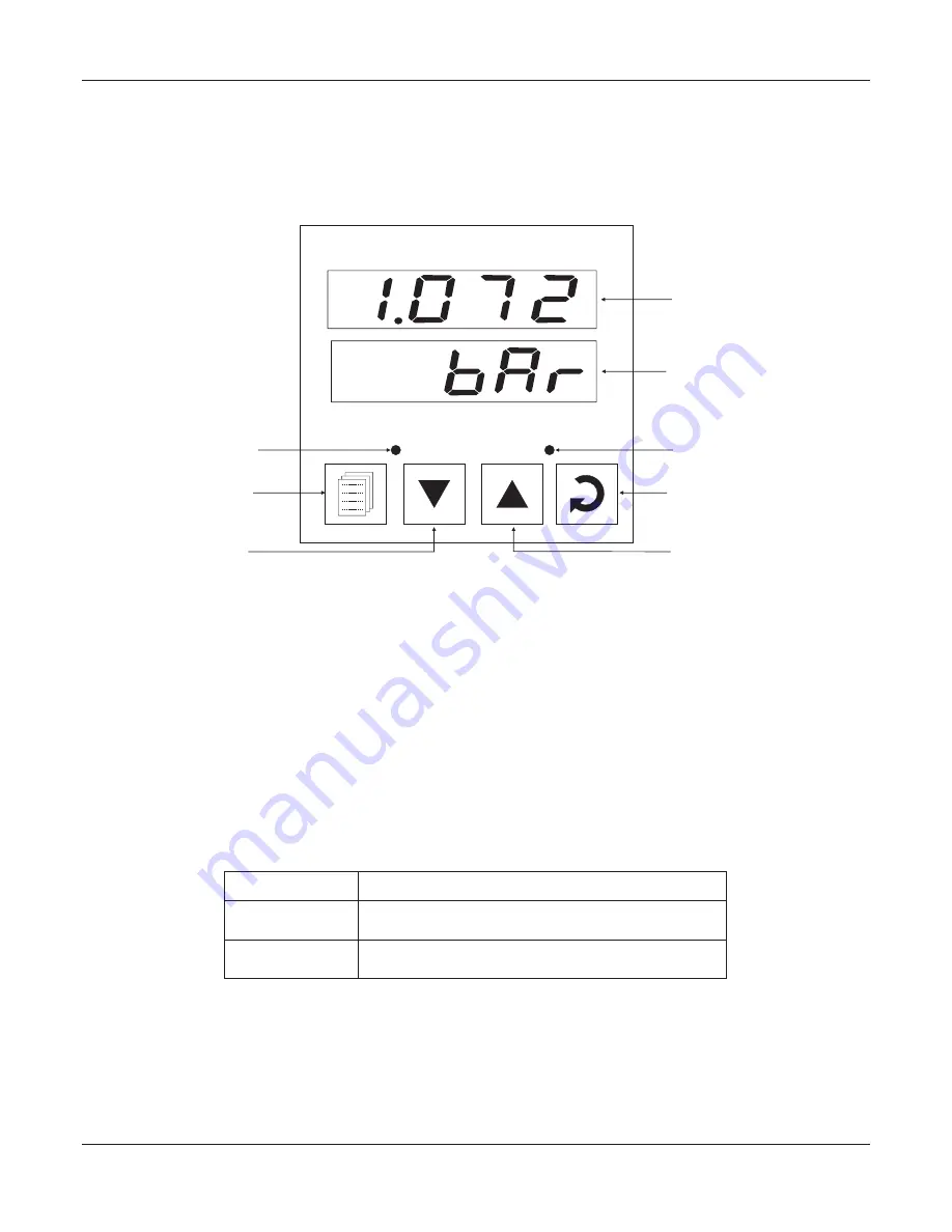
The indicator front panel comprises of digital readouts, LED indicators and membrane keys as shown in Figure 1.1 below.  

FRONT PANEL LAYOUT 

READOUTS

The Upper Readout is a 4 digit, 7-segment bright red LED display and usually displays the PV (Process Value).In Set-up 

Mode, the Upper Readout displays parameter values/options.

The Lower Readout is a 4 digit, 7-segment bright green LED display and usually displays Process Value Units. In case of any 

active Alarm(s), the Lower Readout flashes Alarm Status information. In Set-up Mode, the Lower Readout displays the names 

(identifier tags) for the parameters.

INDICATORS

The front panel comprises 2 LED indicators that show Alarm status. Refer Table 1.1 below for details.

Flashes while Alarm-1 is active. 

AL1 

AL2 

Flashes while Alarm-2 is active.

LED

Status

Table 1.1

KEYS

There are four tactile keys provided on the front panel for configuring the indicator, setting-up the parameter values. Refer 

Table 1.2 below. 

 User Manual

neuro 100 96X96

Section 1 

Figure 1.1

DOWN Key

PAGE Key

Alarm-1 Status

neuro 100

PPI

Upper Readout

Lower Readout

ENTER Key

UP Key

Alarm-2 Status

AL1

AL2

Содержание neuro 100

Страница 1: ...neuro 100 User Manual Universal Process Indicator...

Страница 2: ...RETRANSMISSION PARAMETERS 9 6 INPUT CONFIGURATION 10 7 SUPERVISORY PARAMETERS 14 8 USER LINEARISATION PARAMETERS 16 9 HARDWARE ASSEMBLY CONFIGURATIONS 17 10 MECHANICAL INSTALLATION 23 11 ELECTRICAL C...

Страница 3: ...f any activeAlarm s the Lower Readout flashesAlarm Status information In Set up Mode the Lower Readout displays the names identifier tags for the parameters INDICATORS The front panel comprises 2 LED...

Страница 4: ...ore the set parameter value and to scroll to the next parameter on the PAGE Press to increase the parameter value Pressing once increases the value by one count keeping pressed speeds up the change Pr...

Страница 5: ...pen Under range Over range BASIC OPERATION ALARM STATUS UNDER PV ERROR CONDITIONS For Alarm activation the under range condition is treated as minimum PV whereas the over range and open conditions are...

Страница 6: ...his parameter value to Yes to acknowledge any pending Alarm s to de activate alarm relay s This parameter is available only when any alarm s is active Alternatively use UP or DOWN key to acknowledge p...

Страница 7: ...back to the first parameter 5 Use UP DOWN keys to adjust the parameter value The display flashes if UP key is pressed after reaching the maximum value or DOWN key is pressed after reaching the minimum...

Страница 8: ...enabling disabling the Lock step through the following sequence Locking 1 Press and release PAGE key while the indicator is in the MAIN Display Mode The Lower Readout shows PAGE and the Upper Readout...

Страница 9: ...everse Normal ALARM 1 TYPE Select the Alarm 1 activation type Selecting None will disable the alarm and suppress all the related parameters forAlarm 1 ALARM 1 SETPOINT Sets the Process High or Process...

Страница 10: ...n ALARM 2 INHIBIT Select Normal if Alarm 2 relay is to activate an Audio Visual alarm Select Reverse for tripping cut off the system ALARM 2 LOGIC No The Relay switches ON OFF withAlarm switching Yes...

Страница 11: ...nce with the hardware module fitted Select 0 20 or 4 20 mA if Current output module is fitted Select 0 5 or 0 10 V if Voltage output module is fitted RECORDER OUTPUT TYPE Set the minimum Process Value...

Страница 12: ...ting RESOLUTION Select Temperature units in C or F for Thermocouple or Pt100 sensor For DC Linear input mA mV V Select appropriate Units from the list in Table 6 2 Note however that the selected Units...

Страница 13: ...Kelvin Engineering Units Percentage Pascals Mpascals Kpascals Bar Milli bar PSI kg sq cm mm water gauge Inches water gauge mm mercury Torr Litres per hour Litres per minute Relative Humidity O2 CO2 Ca...

Страница 14: ...wer Readout Units volts Amps Milli amps Milli Volts Ohms Parts per million Revolutions per pinute Milli seconds Seconds Minutes Hours PH PH Miles per hour Milli grams Grams Kilo grams User Manual neur...

Страница 15: ...1 C F 0 to 20mA DC current 4 to 20mA DC current 0 to 50mV DC voltage 0 to 200mV DC voltage 0 to 1 25V DC voltage 0 to 5 0V DC voltage 0 to 10 0V DC voltage 1 to 5 0V DC voltage 3 wire RTD Pt100 1999...

Страница 16: ...ORING This parameter enables or disables the PV monitoring for Min Max values Set to Yes for enabling the feature This parameter allows protection against inadvertent resetting of Min Max values That...

Страница 17: ...ult 1 SERIAL ID NUMBER Unique numeric code assigned to the for identification by indicator the host Set the value as required by the host SERIAL WRITE PERMISSION Setting to No disallows the host to se...

Страница 18: ...r Description Settings Default Value 0 to 9999 Default 0 2 to 32 Default 2 1 to 32 Default 1 1999 to 9999 Default Undefined USER LINEARIZATION SETTING CODE Protection password for access to the linear...

Страница 19: ...c assembly can be removed from the plastic enclosure and placed back as described and illustrated in Figure 9 2 User Manual neuro 100 Figure 9 1 U P U P Front Label Pullout Grip Enclosure Connection D...

Страница 20: ...y from Enclosure With the indicator upright hold the Bezel with the fingers on the pullout grips provided on the left and right sides of the bezel Pull the bezel outward The assembly comes out with th...

Страница 21: ...Alarm Acknowledgment These modules are either pre fitted while the indicator is shipped from the factory or can be fitted by the user later All 3 plug in modules are provided with female socket that...

Страница 22: ...in figures to help locate the plugs for the modules Ensure that the socket snap fits into the plug and the 2 projected parts on the module fit into the 2 slots provided on the Power Supply CPU PCB for...

Страница 23: ...ector Projected Parts Slots Output Module Power Supply Board Front Label Upright neuro 100 Figure 9 6 Mounting Output 3 Module User Manual neuro 100 Output Module Projections P P I Plug Socket Connect...

Страница 24: ...to plug in the Serial Communication Remote Alarm Acknowledgment module To plug or unplug the module simply insert or remove the socket into or from the plug Figure 9 7 Mounting Serial Communication R...

Страница 25: ...static or electromagnetic interference 4 The Indicator should not be subject to direct vibration or shock 5 The Indicator should not be exposed to dust salt air direct sunlight or radiant heat OUTER D...

Страница 26: ...mounting clamp forward until it is firmly in contact with the rear face of the mounting panel and the tongues of the clamp engage in the ratchets on the Indicator enclosure as shown in Figure 10 3 Ens...

Страница 27: ...hort circuits on loads 5 Take care not to over tighten the terminal screws while making connections 6 Make sure that the Indicator supply is switched off while making removing any connections or remov...

Страница 28: ...h the shield grounded at the signal source for connecting mV V source Connect common to terminal 2 and the signal to terminal 1 as shown in Figure 11 2 c Figure 11 2 c 3 2 1 DC Linear Current mA Use a...

Страница 29: ...ndard the indicator is supplied with power connections suited for 85 to 264 VAC Use well insulated copper conductor 2 wire of the size not smaller than 0 5mm for connections Connect Line Phase to term...

Страница 30: ...150 ohm at one end to improve noise immunity REMOTEALARMACKNOWLEDGMENT INPUTS Terminals 14 15 Applicable if the Option plug in module for RemoteAlarmAcknowledge is fitted Use potential free push butt...

Страница 31: ...29 User Manual neuro 100 96X96 neuro 100 96X96...

Страница 32: ...arm s the Lower Readout flashesAlarm Status information In Set up Mode the Lower Readout displays the names identifier tags for the parameters INDICATORS The front panel comprises 2 LED indicators tha...

Страница 33: ...ue and to scroll to the next parameter on the PAGE Press to increase the parameter value Pressing once increases the value by one count keeping pressed speeds up the change Press to decrease the param...

Страница 34: ...CB is to the right and the Display PCB is behind the bezel The electronic assembly can be removed from the plastic enclosure and placed back as described and illustrated in Figure 2 1 Section 2 User M...

Страница 35: ...DC Linear Current or Voltage 4 3 2 1 4 3 2 1 4 3 2 1 Output Type 1 2 3 1 2 3 Jumper Setting C Jumper Setting B OUTPUT 1 Jumper Settings Besides the parameter settings the Output 1 configuration requir...

Страница 36: ...SSR output through proper jumper selection Two jumper settingsAand B as shown in Figure 2 3 are required for Relay or SSR selection ReferTable 2 3 for appropriate jumper setting positions B A Relay SS...

Страница 37: ...nts shown in figure to help locate the plugs for the modules Figure 2 4 The plug for the Serial Communication or Remote Alarm Acknowledgment module is located on the Power supply PCB The Figure 2 5 be...

Страница 38: ...not to over tighten the terminal screws while making connections 6 Make sure that the controller supply is switched off while making removing any connections or removing the controller from its enclo...

Страница 39: ...Use a shielded twisted pair with the shield grounded at the signal source for connecting mV V source Connect common to terminal 2 and the signal to terminal 1 as shown in Figure 3 2 c Figure 3 2 c 3...

Страница 40: ...12 13 Figure 3 5 The indicator is designed for installation in an enclosure which provides adequate protection against electric shock Local regulations regarding electrical installation should be rig...

Страница 41: ...0 to 150 ohm at one end to improve noise immunity REMOTEALARMACKNOWLEDGMENT INPUTS Terminals 14 15 Applicable if the Option plug in module for RemoteAlarmAcknowledge is fitted Use potential free push...

Страница 42: ...a n e t Process Precision Instruments 101 Diamond Industrial Estate Navghar Vasai Road E Dist Palghar 401 210 Maharashtra India 0250 2391722 33 37 42 07498799226 09321985369 support ppiindia net sales...

Отзывы: