Service Manual
Chapter 3 - Commissioning
Validating the Installation
3 - 8
3x3 UPS Commissioning
Issue 2 - November 2001
3. Using a DVM check that the output Voltage and frequency at output Terminals is correct (e.g. 400Vac and
50Hz).
Using a DVM check that the Battery Voltage at the battery Terminals is correct (405V +/- 10V).
4. Close the `MAINS INPUT' MCB (I1).
The UPS should now return to normal Operation.
Ensure that:
D
The `
ć UPS in Operation ć
` returns to the LCD.
D
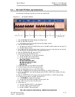
The green `NORMAL' LED ( 1 ) has illuminated,
D
The red `ALARM' LED ( 2 ) has extinguished,
D
The yellow `BYPASS ON' LED ( 4 ) has extinguished
D
The green `LOAD-on-INV' LED ( 3 ) has illuminated.
3.5.3
Test Transfer to the Reserve Line (Automatic Bypass).
Testing the transfer to the reserve bypass line, is carried out by forcing the automatic By-pass circuit to switch and
then checking that the load is still being powered.
If no other alarms occur, the UPS will automatically re-transfer back to inverter operation after 20 seconds on
completion of the test.
1. Press the `MENU' push button (a) on the FRONT PANEL.
a) Select the `COMMAND' screen by pressing either the `BACK' (c) or `NEXT' (b) push button.
b) Confirm the `COMMAND' menu selection by pressing `BACK' and `NEXT' at the same time (i.e. ENTER).
c) Select the `SWITCH LOAD' function by pressing either `BACK' or `NEXT'.
d) Confirm `SWITCH LOAD' function by pressing `BACK' and `NEXT' at the same time.
D
A ***
CONFIRMED***
message will be displayed
2. Press `CLEAR' (d) twice to return to the main menu.
The follow change over sequence will should occur:
D
The yellow `BYPASS ON' LED ( 4 ) will be illuminated (UPS ON BYPASS)
D
After 20 seconds the yellow `BYPASS ON' LED ( 4 ) will turn off and the load will be re-transferred back
to inverter.
D
The green `LOAD on INV' LED ( 3 ) will illuminate (UPS ON INVERTER).

