Service Manual
PCB Replacement Procedures
7 - 33
3x3 UPS
Issue 2 - November 2001
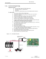
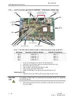
Link and Jumper functions
a)
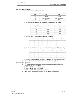
J1ĆJ2ĆJ3 define the UPS characteristics.
Link
Close
Open
J1
OnĆLine
OffĆline
J2
Freq. Tolerance 1%
Freq. Tolerance 4%
J3
50Hz
60Hz
b)
J4ĆJ5 define the parameters of the inverter output voltage and DC Bus voltage.
Output V/Link
J4
J5
Service
close
close
380
open
close
400
close
open
415
open
open
c)
J6ĆJ7ĆJ8 define the overload level related to the UPS ratings
Link
10K
20K
30K
J6
open
close
open
J7
close
open
close
J8
close
close
open
d)
J9ĆJ10ĆJ12 defines the inverter peak current limit for the appropriate UPS output rating.
Link
10K
20K
30K
J9
open
close
open
J10
open
open
close
J12
open
open
open
e)
J11 define the converter peak current limit. (normally closed for all UPS output ratings).
3.
Carry out the Inverter and Converter functional test outlined on page 7-15.
Potentiometer adjustment
4.
It is unlikely that any potentiometer adjustment will be required on a replacement PCB
however the function is listed below.
a)
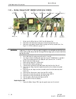
P1 = adjust the inverter output voltage.
b)
P2 = adjust the converter DC voltage.
c)
P3 = adjust the UPS output threshold at
±
15%.
5.
Refit all covers removed and return the UPS to its normal operating condition.


