background image

3.5 Testing And Checking

Make sure the notices included in 1.1 General safety precaution “WARNINGS” has been carefully observed.

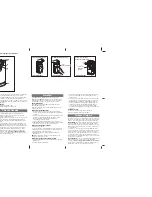
● Release the gearmotor with the proper release key.

● Make sure the gate can be moved manually during opening and closing phases with a force of max. 

   390N (40 kg approx.)

● Lock the gearmotor.

● Using the Key selector switch, push button device or the radio transmitter, test the opening, closing and 

   stopping of the gate and make sure that the gate is in the intended direction.

● Check the devices one by one (photocells, flashing light, key selector, etc.) and confirm the control unit 

   recognizes each device.

Gate Status
Closed
Open 
Stop during moving
Closing
Opening

Photocell 2

Stop opening

No effect

Stop opening

No effect

Closes the leaf

Photocell 1

No effect

Open

No effect

Reloads automatic closing time

Photocell 1/ Photocell 2

Stop opening

Locks and, on release, reverses to open

Locks and, on release, continues opening

Logic F3-1 

                  The reactions of the photocells when detecting obstacles

Gate Status
Closed
Open 
Stop during moving
Closing
Opening

Safety Edge

Stop opening

Stop opening/ closing

Reverses to open for 2 seconds

Reverses to close for 2 seconds

Photocell 1

No effect

Reloads automatic closing time

Open

No effect

Reloads automatic closing time

Logic F3-2 

                  The reactions of the safety edge/ photocell when detecting obstacles

Gate Status
Closed
Open 
Stop during moving
Closing
Opening

Loop Detector

Open

Open
Open
Open

Photocell 1

No effect

Reloads automatic closing time

Open

No effect

Reloads automatic closing time

Logic F3-3 

                  The reactions of the loop detector/ photocell when detecting obstacles

● F3 function settings:

● 

The position of safety devices:

Photocell 1 / Photocell 2

Photocell

Safety Edge

Photocell 1

or

Photocell 1

Loop Detector

Photocell 2

10

 INSTRUCTIONS PL300E/PL400E/PL500E/PL800E SLIDING GATE OPENER USER MANUAL

LED1 Photocells
LED2 Photocells

LED1 will be on when the first pair of the photocells are activated.
LED2 will be on when the second pair of the photocells are activated.

LED Indication                                                                     Descriptions

3.6 Recognition of LED

Содержание PL300E

Страница 1: ...FOR RESIDENTIAL USER MANUAL 24V DC MOTOR SLIDING GATE OPENERS PL300E PL400E PL500E PL800E ...

Страница 2: ...ccording to the following European Directives 2006 42 EC Machinery Directive Comply with the following Standards EN 301489 1 V1 8 1 2008 EN 301489 3 V1 4 1 2002 EN 300220 1 V2 1 1 2006 EN 300220 2 V2 1 2 2007 EN 60335 1 2002 A11 2004 A1 2004 A12 2006 A2 2006 A13 2008 EN 60335 2 103 2003 EN 62233 2008 EN 12445 2001 EN 12453 2001 And also declare that the machinery may not be put into service until ...

Страница 3: ...Learning Reset Process and LED Display 3 4 Programmable Function Settings 3 5 Testing and Checking 3 6 SW2 SW6 Setting 4 Technical Characteriestics 4 1 Technical Data Sheet of Series 4 2 PH 1 Photocell Data Sheet 4 3 PR 1 Transmitter Data Sheet 4 4 PF 1 Flashing Light Data Sheet 4 5 PRB 1 External Receiver Box Data Sheet 5 Additional Information 5 1 Wire Connection of PH 1 Photocell Safety Beam 5 ...

Страница 4: ...ause uncontrolled movement of the driven part due to mechanical failures or an out of balance condition when operating a biased off switch make sure that other persons are kept away when closing a window that has been opened by a fire sensing system make sure that other persons are kept away frequently examine the installation for imbalance and signs of wear or damage to cables springs and mountin...

Страница 5: ...ng light a Operation gear b Limit switch device c 24Vdc motor d Back up batteries Optional e Release device f Control panel g Terminals of devices h Green Box Optional 2 Installation 3 4 2 3 e h f g a b c d 2 2 Description of Device INSTRUCTIONS PL300E PL400E PL500E PL800E SLIDING GATE OPENER USER MANUAL 3 1 ...

Страница 6: ...2 3 Dimension of Device 2 4 Installation of Motor Gear and Gear Rack 100 25 50 25 1 2m 4 INSTRUCTIONS PL300E PL400E PL500E PL800E SLIDING GATE OPENER USER MANUAL ...

Страница 7: ...w Step1 Push the lid of release chamber and move rightward Step2 Insert the key and turn counterclockwise to unlock the device Step3 Turn counter clockwise of the bar to release the motor To restore the automation simply reverse the above procedure Step1 Step2 Step3 NO OK DX SX INSTRUCTIONS PL300E PL400E PL500E PL800E SLIDING GATE OPENER USER MANUAL 5 ...

Страница 8: ...10 11 PPB 1 PPB 1 PKS 1 PKS 1 SW1 SW3 SW4 SW5 3 4 PF 1 PF 1 AC INPUT 1 2 3 4 5 6 7 8 9 1 2 3 4 5 6 AC INPUT 1 2 3 4 5 6 7 8 9 10 11 1 2 3 4 5 6 6 INSTRUCTIONS PL300E PL400E PL500E PL800E SLIDING GATE OPENER USER MANUAL LED2 LED1 AC INPUT 1 2 3 4 5 6 7 8 9 10 11 12 13 14 1 2 3 4 5 6 1 2 3 4 5 6 7 8 9 10 11 12 13 14 C lo s e S to p G N D P b P h P h 2 P h 1 G N D E X T E X T G N D 1 3 7 5 L ig h t O...

Страница 9: ...splay is on then wait for LED display off LED display ON 2 Sec LED display blink twice LED display OFF 1 3 114 ON OFF LED2 LED1 Press 1 3 Sec Press 3 Sec Push 1 2 3 4 5 6 1 LED1 LED2 LED3 ON OFF 2 3 4 5 6 7 8 9 10 11 12 13 14 LED1 LED2 LED3 ON OFF Push 3 seconds 1 2 CAUTION Before proceeding to system learning the transmitter memorizing process has to be completed INSTRUCTIONS PL300E PL400E PL500E...

Страница 10: ...d full speed The deceleration setting for gate moving Deceleration Speed full speed Over current setting 1 2 3 4 5 6 7 1 1 1 2 2 0 2 1 2 2 2 3 2 4 2 5 2 6 2 7 2 8 3 1 3 2 3 3 4 1 4 2 4 3 4 4 5 1 5 2 5 3 5 4 5 5 6 1 6 2 6 3 6 4 6 5 7 1 7 2 7 3 7 4 7 5 7 6 Clockwise Opening Counterclockwise Opening No automatic closing 5 seconds 15 seconds 30 seconds 45 seconds 60 seconds 80 seconds 120 seconds 180 ...

Страница 11: ...when the gate starts to move The flashing light blinks 3 seconds before the gate starts to move Stop Reverse 1 second Reverse 3 second Reverse to the end A key B key C key D key No function in transmitter A key B key C key D key No function in transmitter A key B key C key D key Close Open Close Open Close Open Open Stop Close Stop Open Stop Close 1 The function can adjust the time of opening part...

Страница 12: ...inues opening Logic F3 1 The reactions of the photocells when detecting obstacles Gate Status Closed Open Stop during moving Closing Opening Safety Edge Stop opening Stop opening closing Reverses to open for 2 seconds Reverses to close for 2 seconds Photocell 1 No effect Reloads automatic closing time Open No effect Reloads automatic closing time Logic F3 2 The reactions of the safety edge photoce...

Страница 13: ...on class Dimension Through beam 25 meters 100ms AC DC 12 24V 20 60 IP54 96mm 45mm 43mm 4 1 Techanical Data Sheet Of Series Worm Gear 3500N 3000N 3400RPM 72W 24 Vdc 3A Up to 300 KG 4M 3A for Maximum 10 secs 20o C 50o C 250 170 275mm 7 5kg 24 25 cm s PL300E PL400E Worm Gear 5500N 5000N 3800RPM 144W 24 Vdc 6A Up to 500 KG 6M 5 5A for Maximum 10 secs 20o C 50o C 250 170 275mm 8kg 27 10 cm s Worm Gear ...

Страница 14: ...d 4 on the receiver with the terminals Ph GND and Ph1 on the P600B PCB And use an extra wire to connect terminals 2 and 5 on the receiver as a bridge Detection Method Sensing Range Input Voltage Response Time Emitting Element Operation Indicator Dimensions Output Method Current Consumption Max Water Proof Through Beam 25M AC DC 12 24V 100MS IR LED Red LED RX ON When Beam is Broken Green TX ON 96 4...

Страница 15: ...earn Button for 1 second the LED light should be ON If the LED does not respond please check the cable connection again c Press and hold Button C on the remote for 1 second after the LED is ON The remote completed the memorizing process when LED light turns OFF 3 Device Testing Remote Memorization a Orange cable Signal 1 connect to terminal 10 Pb on the control board b Blue cable GND connect to te...

Страница 16: ...ower saving mode Installation manner AC IN connect the electricity AC OUT connect the power of gate opener and connect the transformer 5V CABLE connect 3 pins white socket of control board Please make sure the switch of Green Box is off before proceeding the system learning and installation of device Wait for the system learning and installation of device to be completed power on the Green Box Gat...

Отзывы: