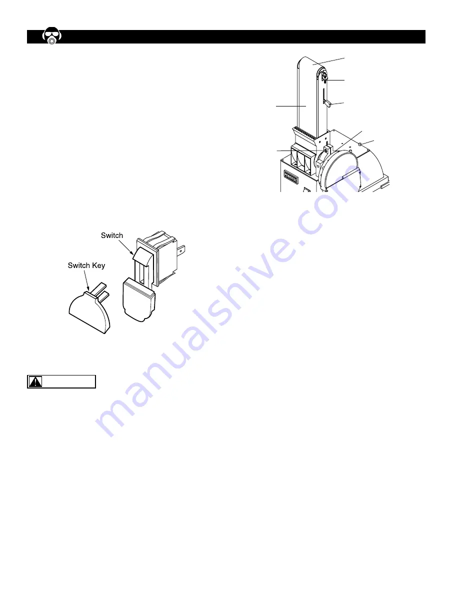
ON/OFF SWITCH
The ON/OFF switch is located in the front of Sander base.
To turn the machine ON, pull the switch to the up position.
To turn the machine OFF, push the switch to the down
position.
NOTE: When the machine is not in use, the machine
should be locked in the “OFF” position to prevent unau-
thorized use.
• To lock the machine, turn the switch to the “OFF”
position and pull the key out. The switch cannot be
turned on without the key.
• If the key is removed when the switch is at the “On”
position, the switch can be turned off but cannot be
turned on again.
• To unlock, place the key into the slot on switch unit until
it snaps.
ADJUST BELT TRACKING MECHANISM
Refer to Figure 9
Keep hands away from sanding belt, idler drum, drive
drum, and any moving parts while conducting Belt
Tracking Mechanism adjustment.
• To check sanding belt level, push the Tension Lever (b)
toward drive drum to tighten the sanding belt.
• To check the belt tracking, switch the machine ON and
OFF quickly. Watch the Sanding Belt (a) movement on
the Idler and Drive Drum. The Sanding Belt should
rotate without moving to the right and left.
• Use the Adjust Tracking Nut (c) to center the Sanding
Belt (a). If the Sanding Belt (a) keeps moving to the
right, turn the Adjust Tracking nut (c) to the left. If the
Sanding Belt (a) keeps moving to the left, turn the Adjust
Tracking nut (c) to the right.
• After each adjustment, switch the machine ON and OFF
quickly and check the Sanding Belt (a) movement again.
Repeat the procedures to adjust the belt tracking until
the Sanding Belt (a) is centered.
ADJUST BELT ASSEMBLY POSITION
Refer to Figure 9
• The Sanding Belt Assembly (d) is designed to function
at any angle between horizontal and vertical position.
There are adjustable positive stops for both horizontal
and vertical positions. The Horizontal Stop is located on
top of the Base (h). It can secure the Sanding Belt
Assembly in horizontal position.
• To change position, use L Wrench to loosen the Socket
Head Bolt (g) in the Pivot Bracket (f). The Pivot Bracket
is located between the Sanding Disc Assembly and The
Sanding belt Assembly.
• Position the Sanding belt Assembly (d) to the desired
angle and tighten the Socket Head Bolt (g) in the Pivot
Bracket (f).
ADJUST TABLE TILT ANGLE
Refer to Figure 10
• The table platform can be adjusted from 0 to 45 degree
(+/- 3°).
• To adjust the table tilt angle, loose the Knob (i) on the
Tilt Angle Scale (k) under the Table Platform (j).
• Tilt the Table Platform (j) to the desired angel as
indicated by the Scale (k). Tighten the Knob (i).
• Check that the distance between the Table Platform (j)
and the sanding surface is 1/16” or less. Do not allow
the sanding surface to touch any part of the Table
Assembly. If adjustment is necessary, loosen the Bolt
(l) that attach the Table Assembly to the Supporting Rod
and adjust the table platform position. Refer to ATTACH
THE TABLE TO USE WITH SANDING BELT section for
details.
Figure 8
Figure 9
OPERATION
6
WARNING
d
g
a
c
b
f
h


