


En
gl
ish
Networking
7
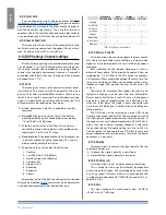
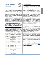
Network capabilities and network setting menus are
available only for k Series amplifiers equipped with a
kaESOp board.
kaESOp stands for k (as in powersoft’s k Series) aES3
and Ethernet Simple Open protocol. powersoft’s kaESOp
is designed to provide high reliability to live applications
in harsh environments where quality of Service must be
guaranteed.
For more details about the aESOp configuration, refer to
the armonía pro audio Suite user guide.
7 : 1.AESOP
7 : 1.1. Data stream
The data stream in the aESOp is implemented by a 100
Mbit Ethernet connectivity with auto-sense.
Each device can use a static ip address assigned by
the user. alternatively, it can be set to automatically config-
ure itself without user intervention following the Zeroconf
protocol.
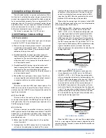
The dual port design in k Series amplifiers allows for
daisy chain and redundant ring topologies. a fault-bypass
built-in feature takes into account the possibility of loosing
an intermediate device or having a faulty cable link without
compromising the ring integrity.
The kaESOp board detects bad quality connections by
counting errors on the Ethernet control. Faulty connections
are automatically switched from 100 Mbit/s to 10 Mbit/s
to attempt to keep the link active even in the worst case
scenarios.
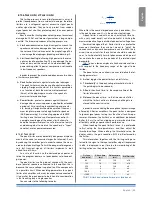
7 : 1.2. Audio
audio is distributed to devices via the aESOp protocol
by 2 independent and separate aES3 streams labeled
aES3-a stream, aES3-B stream. These are carried by two
cat5 wire pairs unused in the 100 Mbit Ethernet protocol.
aES3 is a license free and well known standard guar-
anteeing low-latency, high reliability and excellent audio
quality. a single aES3 stream can carry a stereo audio
signal. The aESOp protocol can therefore handle four audio
channels.
When a k Series amplifier is powered off or if it is una-
vailable, a passive high frequency relay circuit allows the
audio signal to pass through, preserving the network chain
connection integrity.
When the device is powered up, the internal circuits
automatically select the most appropriate aES3 stream di-
rection and bypass the relay, re-buffering actively the aES3
signal. The direction is maintained until errors are detected
on the aES3 receiver circuit. When errors or link failure are
detected, the direction is swapped, to build-up a new path
for the audio. in a fraction of a second (no more than 50ms),
some of the devices in a ring will swap to the other direction,
restoring the audio streaming.
7 : 1.3. Ethernet internal switch
all control data streams in the kaESOp system are
transported via an Ethernet protocol. inside to all k Series
amplifiers is an Ethernet switch connected to each rJ45.
This means that the bidirectional data stream can enter/
exit one port and exit/enter any other port, either alongside
aES3 streams or on its own.
internal routing of Ethernet networking is automatic and
not user controllable. an internal switch provides packet
flooding block services in order to allow building networks
with a ring topology.
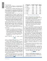
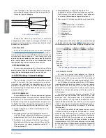
7 : 1.4. Forwarding and repeater modes
Each k Series amplifier can be configured to handle the
pair of aES3 streams embedded in the aESOp protocol in
one of two basic network modes: repeater and forwarder.
These are true connection “building blocks”; it is there-
fore important to understand these two modes thoroughly
before attempting to create or modify larger and more com-
plex amplifier networks.
The following are definitions of the terms used in this
section:
f
f
AES3-A stream
: aESOp digital audio stream a (two
channels)
f
f
AES3-B stream
: aESOp digital audio stream B (two
channels)
f
f
AES3-XLR stream
: aES3 digital audio stream via the
rear panel XLr connector.
f
f
PORT 1, PORT 2
: primary rJ45 aESOp ports
f
f
PORT 3, PORT 4
: secondary rJ45 Ethernet ports
For more details about aESOp configuration, refer to the
armonía pro audio Suite user guide.
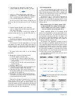
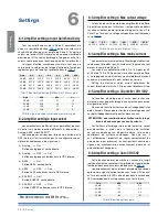
7 : 2.Network settings
The Network settings menu become available when the
kaESOp board is installed.
Many of the menus in this section require the user to
select one functioning mode from a set of possible alterna-
tives. These alternatives are all presented in a list. a black
diamond shape next to a specific item in the list indicates
that that is the selected option.
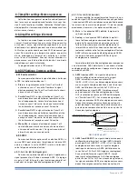
f
f
Device mode
: this parameter sets the amplifier mode
with respect to the aES3 stream. available options are:
repeater (default); Forward to aES3-a;
Forward to aES3-B;
Forward to both.
Note: when an amplifier is in forward mode (either to
aES3-a, aES3-B or both) the amplifier can only accept the
aES signal coming from the aES3-XLr connector. aES3
streams incoming from any other rJ45 port are ignored.
f
f
Addressing Mode
: this parameter controls the ip ad-
dressing assignment strategy:
Manual
: requires the user to set a valid static ad-
dress and subnet mask (and, optionally, the default
English | 33
Содержание K2 DSP+AESOP, K3 DSP+AESOP
Страница 4: ...Page intentionally left blank 2 K Series...
Страница 8: ...A K2 K3 K2 DSP AESOP K3 DSP AESOP 465 32 2 496 456 5 9 482 439 44 32 6 K Series...
Страница 10: ...C D E K2 K3 K2 DSP AESOP K3 DSP AESOP 8 K Series A F B C D E G 1 2 9 3 5 14 4 13 6 7 12 8 10 11...
Страница 12: ...F G K6 K8 K10 K20 K6 DSP AESOP K8 DSP AESOP K10 DSP AESOP K20 DSP AESOP 10 K Series 1 2 4 12 3 11 5 6 10 7 8 9...
Страница 88: ...Page intentionally left blank 86 K Series...
Страница 89: ...Page intentionally left blank Specifications 87...
Страница 90: ...Page intentionally left blank 88 K Series...
Страница 91: ......