

En
gl
ish
LEDs and
display menu
5
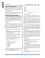
in all k Series amplifiers, the combination of the front
panel buttons together with the LcD display allow the user
access to detailed information and complete control over
the amplifier’s status. Each button has multiple functions
and the display shows the current active function for each
button. This chapter illustrates all the functions and settings
accessible via the amplifier front panel.
all the setup and settings functions described in this
section can be also accessed through a computer with
powersoft’s armonía pro audio Suite software. armonía is
a software environment that offers an easy to use end user
remote control interface and signal processing capabilities.
armonía pro audio Suite is available for free on the
armonía forum:
http://www.powersoft-audio.com/en/armonia-forum
please note that when an armonía client is connected to the
amplifier, any local operation is overridden by the software.
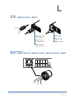
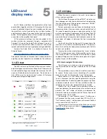
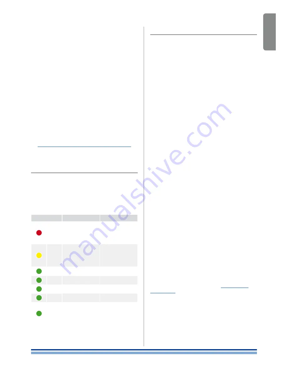
5 : 1.LED chart
The LED columns on the front of the amp can work as
output voltage or current meters. When the LED bars are set
to meter output voltage, for example, the meters on the LcD
screen will indicate output current values. The vice versa is
true: LED bars set as output current meters, LcD display
bars become output voltage meters.
Color
Solid
Blinking
rED
Signal clipping
Or
channel muted
for protection
1
Tone
detection
problem
YELLOW
Temperature
above 85°c
Or
output level
2
-2 dB
critical
temperature
(80° - 85°c)
GrEEN
output level
2
-3 dB
GrEEN
output level
2
-6 dB
GrEEN
output level
2
-9 dB
GrEEN
output level
2
-15 dB
GrEEN
input signal is above
-60 dBV
Or
output level
2
-18 dB
1
in case of a short circuit protection event, the LcD screen will read “prOT”.
2
With respect to the output clipping threshold.
TAB. 1: LED chart.
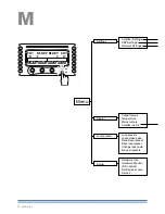
5 : 2.Front display
When the amp is turned on, the main screen appears
after a short presentation.
The first line of the screen will read “WaiT” while the sys-
tem undergoes an initial batch of internal tests to determine
the status of the amp. if all parameters are normal, “rEaDY”
will replace “WaiT” on the display.
System parameters are continuously monitored by the
internal controller. if any parameter value should fall out of
its correctly operating range, a code error relative to that
particular parameter will appear on the third line of the LcD
meter at the corresponding channel number. Should the
parameter be out of range for both adjacent channels, the
error code will appear in between the two compromised
channels.
The fourth line of the front panel LcD screen shows the
functions of the buttons immediately below. a beep con-
firms that a button has been pressed; please note that this
sound is not mutable.
pressing the button directly below the “menu” label on
the LcD screen gives access to the amplifier’s main menu.
if an armonía client is connected to the amplifier, a yellow
shadow will appear in the software workspace view, signal-
ing local access to the amplifier.
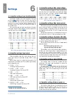
5 : 2.1. How to navigate the main menu
The k Series main menu can be accessed by press-
ing the first button on the right, underneath the LcD label
“menu”.
The up and down arrows allow to scroll the menu items.
To access further menu voices branching off a specific
menu item, select it and press the “menu” button once.
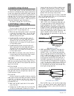
Some submenus in the k Series amps require the user
to set a numerical value for specific parameters using the
front panel buttons. in order to speed this process up, these
submenus dedicate two of the four available buttons to
switching to a fast or slow parameter increment mode.
When in the “slow” mode, the up and down arrows in-
crease or decrease the parameter by a the smallest amount
possible. The “fast” mode will increase or decrease the
parameter value by an amount equal to 10 times the amount
increased in the “slow” mode.
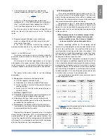
For example: in “slow” mode a single “+” button press
will increase the Max mains current from 22 a to 23 a; in
“fast” mode a single “+” button press will increase the Max
mains current from 22 a to 32 a.
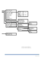
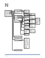
The overview of the structure of the Main menu and of
the DSp settings menu are shown in
panel M, p. 14
and
panel N, p. 16
respectively.
English | 25
Содержание K2 DSP+AESOP, K3 DSP+AESOP
Страница 4: ...Page intentionally left blank 2 K Series...
Страница 8: ...A K2 K3 K2 DSP AESOP K3 DSP AESOP 465 32 2 496 456 5 9 482 439 44 32 6 K Series...
Страница 10: ...C D E K2 K3 K2 DSP AESOP K3 DSP AESOP 8 K Series A F B C D E G 1 2 9 3 5 14 4 13 6 7 12 8 10 11...
Страница 12: ...F G K6 K8 K10 K20 K6 DSP AESOP K8 DSP AESOP K10 DSP AESOP K20 DSP AESOP 10 K Series 1 2 4 12 3 11 5 6 10 7 8 9...
Страница 88: ...Page intentionally left blank 86 K Series...
Страница 89: ...Page intentionally left blank Specifications 87...
Страница 90: ...Page intentionally left blank 88 K Series...
Страница 91: ......