


En
gl
ish
2. calculate the power delivered to a speaker with
nominal impedance of 8 ohm with that
V
rms
voltage:
where
P
equiv
is the equivalent power on the 8 ohm
speaker and
V
rms
is the rMS voltage value calculated at
step 1. in this example (4 ohm speaker) this is 250 W.
This is the threshold power to set in the limiter.
The time constants for the power vs voltage @ 8 ohm
limiter can be set in the same way as for the Truepower
limiter.
f
f
Power vs current @ 8 ohm
: similar to the case
power vs voltage @ 8 ohm, but based on the current
measured at the output.
in this case the formula to derive the average or
continuous power, known as
P
rms
from the rMS current is:
where
I
rms
is the rMS current.
This limiter is particularly useful in situations where the
parameter to be controlled is the output current (e.g. for
tweeters).
it is also useful for special applications such as large
coil speakers with current controls. When determining this
limiter’s parameters, it is necessary to take into account the
number of speakers connected in parallel to the amplifier.
The power limiter menu allows to set the following
parameters:
f
f
Mode
: allows to determine the power limiter
f
f
OFF/ON: toggle le limiter on or off;
f
f
Truepower: sets the limiter mode to Truepower
f
f
power vs V @ 8 Ω: sets the limiter mode to power vs
voltage @ 8 ohm
f
f
power vs i @ 8 Ω: sets the limiter mode to power vs
current @ 8 ohm
f
f
Soft knee
: toggle ON/OFF
f
f
Thresh.(W)
: threshold output power level expressed in
watt at which the gain begins to be reduced;
f
f
Attack (ms)
: the time it takes for the limiter to start
reducing the amplifier gain once the output power has
exceeded the threshold value;
f
f
Release (ms)
: the time constant after which the gain
is restored to its nominal value once the output power
has returned below the threshold.
When editing the power threshold value, the display
shows the gain reduction (Gr) in dB enforced by the
combined effect of the peak and power limiters. This
information, together with the average power truly delivered
to the load (
P
avg
), is displayed in real time to allow monitoring
of the limiting actions as they are performed.
6 : 10.7. Damping Control
This unique and patented feature allows to add a “vir-
tual” series resistor to the amplifier output. This is done to
obtain the desired damping factor with any cabling used.
For this end, the virtual series resistor can also have a nega-
tive value to compensate cabling resistance.
For example, using a 10 meter cable to powering the
subwoofer means adding a series parasitic resistance of
about 0.3 ohm. By enabling the damping control, a virtual
negative series resistance can be added to compensate the
cable resistance.
When damping control is enabled, a lowpass filter
cutting around 400 Hz is automatically inserted
into the amplifier chain. This feature is intended
to be used only for subwoofer applications.
another advantage offered by the damping control
feature is that in adding the series equivalent output resist-
ance to the amplifier chain, the variation of the voice coil
resistance due to heating can be taken into account. This
allows to obtain a correctly damped bass response at aver-
age working condition, where the voice coils is subject to
heating due to the passage of current.
For example, if the subwoofers are going to work at
close to full power, an additional negative resistance of 1 to
2 ohm should be added to compensate the high resistance
generated by the heated voice coils to obtain a correctly
damped response. On the other hand, if the same subwoof-
ers are working at low power, a smaller negative resistance
should be added: in this case the cooler voice coil presents
a smaller series resistance to be compensated.
Leaving too high an equivalent series resistance results
in an overdamped system.
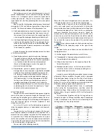
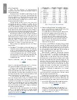
Section area
(mm
2
- AWG)
Nominal
resistance
Length
(m)
Resistance
(ohm)
2 x 1.5 - 16 aWG
r = 12 Ω/km
5
0,12
10
0,24
20
0,48
2 x 2.5 - 13 aWG r = 7.4 Ω/km
5
0,07
10
0,15
20
0,30
2 x 4 - 11 aWG
r = 4.5 Ω/km
5
0,05
10
0,09
20
0,18
TAB. 9: Typical speaker cabling resistance.
Average power/
rated power
Power
compression
Equivalent series
resistance
to a 8
Ω driver
10%
1.4 dB
1.0 Ω
20%
2.0 dB
1.4 Ω
50%
2.8 dB
2.1 Ω
100%
4.5 dB
3.8 Ω
TAB. 10: Typical resistance increase
due to voice coil heating.
On
TaB. 10
notice the exceptionally high value (3.8 ohm)
when the driver reaches it thermal limit.
P
equiv
=
8
V
2
rms
P
rms
= I
2
rms
∙
Re
English | 31
Содержание K2 DSP+AESOP, K3 DSP+AESOP
Страница 4: ...Page intentionally left blank 2 K Series...
Страница 8: ...A K2 K3 K2 DSP AESOP K3 DSP AESOP 465 32 2 496 456 5 9 482 439 44 32 6 K Series...
Страница 10: ...C D E K2 K3 K2 DSP AESOP K3 DSP AESOP 8 K Series A F B C D E G 1 2 9 3 5 14 4 13 6 7 12 8 10 11...
Страница 12: ...F G K6 K8 K10 K20 K6 DSP AESOP K8 DSP AESOP K10 DSP AESOP K20 DSP AESOP 10 K Series 1 2 4 12 3 11 5 6 10 7 8 9...
Страница 88: ...Page intentionally left blank 86 K Series...
Страница 89: ...Page intentionally left blank Specifications 87...
Страница 90: ...Page intentionally left blank 88 K Series...
Страница 91: ......