powersoft K2 DSP+AESOP, K3 DSP+AESOP Скачать руководство пользователя страница 32

En

gli

sh

6 : 10.6.2. Power limiter

Given the low efficiency of electromechanical 

transducers, almost 50% of power reaching the voice coil is 
transformed into heat.

The power limiter is intended to avoid melting the voice 

coils of drivers while at the same time exploiting their 
maximum performance, therefore the power limiter should 
not be engaged at normal working levels. The power limiter 
acts by decreasing the amplifier’s gain in order to reduce 
the power delivered to the load.

a correct power limiting is not an easy task and is 

multifaceted, based on a number of variable, like the 
knowledge of the component heat dissipation and the goals 
that must be achieved. Therefore may be difficult and a little 
bit empirical decide thresholds and constants time. power 
limiters behavior base their operations on a mix based on 
threshold, dynamic behavior of the output readings (voltage 
and current) and the type of output readings monitored.

check the gain reduction: in order to obtain the optimal 

sound it should not be greater than 2-4 dB even for the 
loudest piece of music. please note that a common musical 
signal has very high peaks, but a rather small average level 
(high crest factor). a stationary tone has a much higher 
average power (e.g. a stationary sine wave has 3 dB crest 
factor) even if it “sounds” less loud to the human ear. 

There are three main operating modes for the k Series 

power limiters.

f

f

TruePower™

: the amplifier’s active output power is es-

timated by measuring the load current. The Truepower 
limiter is a powersoft patent technology useful to avoid 
overheating of the voice coil; it can however also be 
used to avoid power compression. The DSp provides 
the measurement of the real power delivered (and then 
dissipated) to the coil, ignoring the apparent power 
handled by the line.

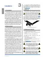
Empirical observation yields the following equation 

where 

P

AES

 is the declared aES power and 

P

max

 is the maxi-

mum power the speaker can dissipate “in real life”.

if the 

P

AES

 is not available, the average or continuous 

power, known as 

P

rms

 can be used as well; however, it is 

important to proceed with caution in evaluating how the 

P

rms


value is obtained. if no other values are declared, this rule of 
the thumb can be used: the 

P

AES

 can be estimated as 6 dB 

below the peak power (¼ of the peak power).

it is very important to note that, contrary to what hap-

pens with the peak limiter, setting the Truepower limiter 
parameters must take into account the number of speakers 
connected to the amplifier. This is due to the fact that the 
real power is calculated not only with the output voltage 
(which is identical for all speakers connected in parallel) but 
also with the output current (which changes according to 
the number of parallel speakers).

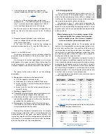
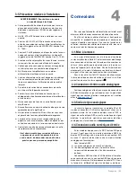
Determining the ideal time parameters for Truepower 

limiters is a very empirical process. as a guide, consider 
this simple rule: larger the coil, larger the thermal inertia, 
larger the time constant (ref. 

TaB. 8

).

f

f

Power vs voltage @ 8 ohm

: the amplifier’s output 

power is estimated by measuring the rMS value of the 
output voltage, assuming an 8 ohm load. 
This mode allows to create settings that work well for 
any number of speakers connected in parallel. For 
example, if a “power @ 8 ohm” limiter is set to limit 
the output power to 150 W, a single cabinet will be 
delivered a maximum of 150 W with 8 ohm load. Two 
speaker cabinets connected in parallel will be deliv-
ered a maximum of 300 W with 4 ohm load (8 ohm 
loads in parallel) and so on.

This limiter is a pure rMS limiter whose functioning is based 
solely on the voltage module measured at the amplifier out-
put. Differently from the Truepower limiter, this limiter does 
not take into account the real part of the power; however, it 
has the advantage of being independent from the number of 
cabinets linked together, just as a peak limiter.

Some attention is needed to set the power threshold. 

The 

P

AES

 can be used if it is available. if no other power rat-

ing is declared, the 

P

rms

 can be used as well; however, the 

rMS parameter is a value related to the maximum manage-
able power and not the real power. proceed with caution 
because the manageable power could be greater than the 
real power. Some constructors declare the rMS power at 
the minimum impedance point of the speaker; this, again, 
may lead to an overestimation of the true power values the 
speaker can handle. if no other values are available, the 
following rule of the thumb can be used: the 

P

rms

 can be 

estimated as 6 dB below the peak power (¼ of the peak 
power).

in order to preserve the driver in the long term, once the 

maximum power limit is decided upon, consider a power 
reduction of up to 3 dB of that value.

in order to use this limiter correctly, it is important to re-

calculate the equivalent power at 8 ohm. For example, with 
an 4 ohm speaker with 500 W maximum rMS power, the 
equivalent power at 8 ohm needs to be calculated as follow: 

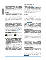
1.  calculate the rMS voltage value needed to generate 

the maximum rMS power on the 4 ohm speaker: 

Voice coil size  

(inches)

Threshold 

(W)

Attack time 

(ms)

Release 

time (ms)

1”

tweeter

10-20

100

300

1.5” tweeter

20-30

150

300

2”

comp. driver

20-40

200

400

3”

comp. driver

30-50

300

500

4”

com. driver

40-60

500

3000

2”

midange

30-100

500

3000

3”

midbass

50-150

1000

5000

4”

woofer

100-200

2000

5000

4”

woofer

150-250

4000

8000

6”

woofer

250-500

6000

10000

TAB. 8: Threshold and time parameters.

where 

V

rms

 is the rMS voltage of the speaker, 

P

rms

 is 

its average or continuous power and 

Re

 the nominal 

impedance. in the above example the rMS voltage of 
the 4 ohm speaker is 

V

rms

 = 44.7 V.

V

rms

 = √ 

Re

 ∙ 

P

rms

P

max

 =

3

P

AES

30 | K Series

Содержание K2 DSP+AESOP, K3 DSP+AESOP

Страница 1: ...l for future reference 2016 Powersoft K Series S rie K Serie K DO000208 00 R00 quick GUIDE Guide rapide gu a r pida K2 K3 K2 DSP AESOP K3 DSP AESOP K6 K8 K10 K6 DSP AESOP K8 DSP AESOP K10 DSP AESOP K2...

Страница 2: ...iamenti senza preavviso Per gli aggiornamenti si prega di consultare la versione inglese disponibile online su www powersoft audio com http www powersoft audio com http www powersoft audio com Alle An...

Страница 3: ...Espa ol English Fran aise 20 40 60 K Series S rie K Serie K Table of contents 3 Table des mati res 4 Tabla de contenido 5 Regulatory information 19 K Series 1...

Страница 4: ...Page intentionally left blank 2 K Series...

Страница 5: ...0 3 Polarity 28 6 10 4 Ch Delay us 28 6 10 5 Gain 28 6 10 6 Peak Limiter et Power Limiter 29 6 10 7 Damping Control 31 6 11 DSP Settings Ch1 setup Ch2 setup 32 6 11 1 Aux Dly ms 32 6 11 2 Diagnostics...

Страница 6: ...1 EQs Egaliseurs 48 6 10 2 Filters LP et HP 48 6 10 3 Polarity 49 6 10 4 Ch Delay us 49 6 10 5 Gain 49 6 10 6 Peak Limiter et Power Limiter 49 6 10 7 Damping Control 52 6 11 DSP Settings Ch1 setup Ch2...

Страница 7: ...res 68 6 10 2 Filters LP and HP 68 6 10 3 Polarity 69 6 10 4 Ch Delay us 69 6 10 5 Gain Ganancia 69 6 10 6 Peak Limiter et Power Limiter 69 6 10 7 Damping Control 72 6 11 DSP Settings Ch1 setup Ch2 se...

Страница 8: ...A K2 K3 K2 DSP AESOP K3 DSP AESOP 465 32 2 496 456 5 9 482 439 44 32 6 K Series...

Страница 9: ...B K6 K8 K10 K6 DSP AESOP K8 DSP AESOP K10 DSP AESOP K20 K20 DSP AESOP 465 32 2 465 4 472 4 5 9 482 440 44 32 K Series 7...

Страница 10: ...C D E K2 K3 K2 DSP AESOP K3 DSP AESOP 8 K Series A F B C D E G 1 2 9 3 5 14 4 13 6 7 12 8 10 11...

Страница 11: ...ogique pour l entr e 2 6 Entr e 2 le canal d entr e 2 analogique en mode analogique ou l entr e AES3 en mode AES3 selon la position du commutateur 5 7 Sortie ligne canal 2 8 Bouton Link lien entr e de...

Страница 12: ...F G K6 K8 K10 K20 K6 DSP AESOP K8 DSP AESOP K10 DSP AESOP K20 DSP AESOP 10 K Series 1 2 4 12 3 11 5 6 10 7 8 9...

Страница 13: ...n mode analogique ou l entr e AES3 en mode AES3 selon la position du commutateur 5 7 Bouton Link lien entr e des canaux 1 et 2 8 Entr e 1 entr e analogique du canal 1 9 Connecteur de haut parleur sort...

Страница 14: ...log line output XLR F pinout Pin 1 GND Pin 2 HOT Pin 3 COLD HOT 1 2 3 COLD GND Bridge tied load speakON connector Channel 2 output stage B LINK CHB CHB CHB CHB B speakON connector Channel 1 output sta...

Страница 15: ...P AESOP Open the lock and insert the plug Ouvrir le verrou et ins rer la fiche Abra el seguro y conecte la clavija Lock the plug Bloquer la fiche Asegure la clavija L ground mains N Neutral L Line GND...

Страница 16: ...s Amplifier Settings DSP Settings1 Network Settings2 Output meters Temperature Mains meters Amplifier name Lock presets Locked bank size Recall local preset Save local preset Change lock code Erase al...

Страница 17: ...tput attenuation Input gain sens Inuput select Max output voltage Max mains current Clip limiter CH1 Clip limiter CH2 Gate CH1 Gate CH2 Mute at Power on Idle Mode see DSP Settings diagram Device mode...

Страница 18: ...esh Vpk Attack ms Release ms Mode Soft knee Thresh W Attack ms Release ms Mode Equiv Rout Aux Dly ms Diagnostics Tone in alarm Tone in freq Tone in Vmin Tone in Vmax Tone out gen Tone out ampl Tone ou...

Страница 19: ...TER CHANNEL DELAY FIR EQ Output current Output voltage output monitor 16 bands parametric EQ Custom FIR Enhanced limiter Cable loss compensation IIR and FIR linear phase crossover CHANNEL PEQ16 Load i...

Страница 20: ...P Q 1 1 1 RU 1 RU 1 RU Mounting brackets Soportes de montaje Supports de fixation 1 1 2 2 2 2 3 3 3 3 4 4 4 4 5 18 K Series...

Страница 21: ...the user s responsibility to dispose of their waste electrical and electronic equipment by handing it over to an approved reprocessor or by return ing it to Powesoft S p A for reprocessing For more i...

Страница 22: ...mbers 9 and 13 apply only to K2 and K3 WARNING TO REDUCE THE RISK OF ELECTRIC SHOCK DO NOT ATTEMPT TO OPEN ANY PART OF THE UNIT NO USER SERVICEABLE PARTSINSIDE REFERSERVICINGTOQUALIFIEDSERVICEPERSONNE...

Страница 23: ...utput power without having to change amplifier K Series amplifiers are K2 K2 DSP K3 K3 DSP K6 K6 DSP K8 K8 DSP K10 K10DSP K20 K20DSP 8 1000 W 1400 W 1300 W 1500 W 2000 W 2700 W 4 1950 W 2600 W 2500 W...

Страница 24: ...hannels until the amplifier cools down to a safe operating temperature Normal operation is resumed automatically without the need for user intervention K Series amplifiers can be stacked one on top of...

Страница 25: ...nced differential digital signal in AES3 XLR connectors the identification of hot and cold pins is not an issue Avoid the use of microphone cables in AES connections impedance mismatch can result in s...

Страница 26: ...channel 1 needs to be wired link channel 2 to channel 1 by means of the link pushbutton located on the rear panel When operating with digital inputs i e AES3 and AESOP link the channels through Armon...

Страница 27: ...ternal tests to determine the status of the amp If all parameters are normal READY will replace WAIT on the display System parameters are continuously monitored by the internal controller If any param...

Страница 28: ...ge The max output peak voltage of K Series amplifiers can be set by the user It is possible to set output peak voltage levels for channel 1 channel 2 or both Available voltage ranges for each model ar...

Страница 29: ...g signals should be carefully matched This can be done using the gain trim parameter or by adjusting the analog signal level f f AES3 from KASEOP the primary audio signal for this configuration is an...

Страница 30: ...4 Low pass EQ 5 High pass EQ 6 Bandstop 7 Bandpass 8 Allpass By pressing the edit button the settings for the selected filter can be modified TAB 6 summarizes which parameters can be edited according...

Страница 31: ...with the num ber of parallel speakers connected to the amplifier this is because the same voltage is applied to all the components in a parallel circuit When deciding parameters for a peak limiter of...

Страница 32: ...according to the number of parallel speakers Determining the ideal time parameters for TruePower limiters is a very empirical process As a guide consider this simple rule larger the coil larger the th...

Страница 33: ...limiting actions as they are performed 6 10 7 Damping Control This unique and patented feature allows to add a vir tual series resistor to the amplifier output This is done to obtain the desired damp...

Страница 34: ...tput tone detection can measure the presence of a tone generated by an external or internal generator Tone out alarm enable disable the output tone detec tion Tone out Vmin the minimun detected thresh...

Страница 35: ...h for the audio In a fraction of a second no more than 50ms some of the devices in a ring will swap to the other direction restoring the audio streaming 7 1 3 Ethernet internal switch All control data...

Страница 36: ...et as KAESOP OUT or KAESOP DSP OUT The two possible alternatives are Mute and Analog In Analog mode the amplifier automatically switches to CH1 CH2 analog input if the digital stream is missing return...

Страница 37: ...o an empty slot To save the current amplifier setup as a preset to the local memory enter the Save local preset menu Select an empty preset location press ok and define a proper name If no other prese...

Страница 38: ...nal auxiliary voltage f f 5VAN auxiliary analog voltage f f VEXT external remote control voltage f f VAUX indicates if the power supply auxiliary voltage is correct f f IGBTCONV indicates the DC DC co...

Страница 39: ...r in mind that Ethernet is a faster communica tions protocol than serial RS 485 The range of network topologies which can be used in wiring a real system varies between the two communica tions methods...

Страница 40: ...om defective components and factory workmanship for a period of 48 forty eight months starting from the date of purchase printed on Powersoft s or any of its Authorized Dealer s invoice to the end cus...

Страница 41: ...rsoft it for Powersoft approval f f In case of defect reports approved by the Powersoft Customer Service Representative you will receive an RMA authorization code one RMA code for each re turning devi...

Страница 42: ...he sont endommag s si du liquide ou tout autre corps tranger a p n tr dans l appareil si l appareil a t expos la pluie ou l humidit s il ne fonctionne pas normalement ou s il est tomb Num ros 9 et 13...

Страница 43: ...Les amplificateurs de la S rie K sont K2 K2 DSP K3 K3 DSP K6 K6 DSP K8 K8 DSP K10 K10DSP K20 K20DSP 8 1000 W 1400 W 1300 W 1500 W 2000 W 2700 W 4 1950 W 2600 W 2500 W 3000 W 4000 W 5200 W 2 2400 W 28...

Страница 44: ...thermique extr me le ventilateur force un volume impor tant d air travers le dissipateur de chaleur Au cas tr s improbable o l amplificateur venait surchauffer dangere usement les capteurs couperaien...

Страница 45: ...mp tente Connexions 4 S assurer que l interrupteur d alimentation soit teint avant d essayer d effectuer des connexions d entr e et de sortie En utilisant de bons c bles d entr e et haut parleurs de q...

Страница 46: ...t SpeakOn pour les connexions pont es ou st r o comme illustr sur les figures suivantes CLASS3 WIRING CLASS2 WIRING 4 6 1 Connexion en mode pont La connexion des sorties en mode Pont peut tre r ali s...

Страница 47: ...ra t apr s une br ve pr sentation La premi re ligne de l cran indique WAIT pendant que le syst me subit une premi re s rie de tests internes afin de v rifier l tat de l ampli Si tous les param tres so...

Страница 48: ...cr te des amplificateurs de S rie K peut tre ajust e par l utilisateur Il est possible de d finir les niveaux de tension de sortie de cr te pour le Canal 1 le Canal 2 ou les deux Les plages disponibl...

Страница 49: ...mme peu fiable quand les erreurs de transmission d passent 1 de l ensemble des donn es transmises Les options possibles sont f f Mute si la connexion AES3 d faille l ampli met la sortie en sourdine f...

Страница 50: ...ement haut de 3 15 dB oct 4 EQ passe bas 5 EQ passe haut 6 Arr t Bande 7 Bande passante 8 Allpass En appuyant sur le bouton edit vous pouvez changer les r glages du filtre s lectionn TAB 6 indique que...

Страница 51: ...male pendant laquelle la puissance peut tre appliqu e avec s curit aux haut parleurs Une approche int ressante de la limitation RMS est celle qui fait appel au contr le de temp rature de bobine Une co...

Страница 52: ...l ordinaire a de tr s hautes cr tes mais un niveau moyen relativement petit facteur de cr te lev e Une tonalit stationnaire a une puissance moyenne bien plus haute par exemple une onde sinuso dale sta...

Страница 53: ...u haut parleur et Prms est sa puissance RMS maximum La tension RMS du haut parleur 4 dans l exemple ci dessus est Vrms 44 7 V 2 culez la puisance d livr e un haut parleur d une imp dance nominale de 8...

Страница 54: ...e typique augmente en rai son de l chauffement de la bobine mobile Dans la TAB 10 remarquez la valeur exceptionnellement haute 3 8 ohm quand le circuit d attaque atteint sa limite thermique 6 11 DSP S...

Страница 55: ...pen Protocol Le KAESOP de Powersoft est con u pour fournir une haute fiabilit aux applications en direct dans des environnement difficiles o la qualit du service doit tre garantie Pour plus de d tails...

Страница 56: ...se statique valide et un masque de sous r sau et optionnellement la passerelle par d faut Le PC doit tre sur le m me sous r seau que l ampli si aucun routeur n est pr sent entre le PC et l ampli Autom...

Страница 57: ...en gras clignotant sur un second cran qui indique le nom pr r gl actuellement s lectionn 40 caract res Si le pr r glage a t modifi le nom pr r gl affich aura un pr fixe Modified pour signaler ce poin...

Страница 58: ...eau arri re Une pression sur le bouton more sur l cran permet de naviguer parmi d autres pages contenant d autres informations le bouton back vous fait revenir au menu d installation ant rieur f f KFR...

Страница 59: ...en armonia forum La communication logiciel ampli est assur e via une connexion RS 485 ou Ethernet selon les ports disponibles Armon a permet le contr le et la surveillance d un large ventail de fonct...

Страница 60: ...in stocker et partager des configurations et pr r glages pour l amplificateur jusqu 150 pr r glages peuvent tre stock s dans une seule carte et facilement partag s entre les diff rents amplificateurs...

Страница 61: ...t des co ts inh rents au renvoi des marchandises l acheteur ou utilisateur client final 13 2 Assistance Bien que la majorit des dysfonctionnements du produit puisse tre r solue dans vos locaux gr ce l...

Страница 62: ...arato el aparato ha sido expuesto a la lluvia o humedad si no funciona con normalidad o se ha ca do Los n meros 9 y 13 son aplicables s lo a K2 y K3 Instrucciones de seguridad importantes 1 ADVERTENCI...

Страница 63: ...a de salida sin tener que cambiar el amplificador Los amplificadores de la Serie K son K2 K2 DSP K3 K3 DSP K6 K6 DSP K8 K8 DSP K10 K10DSP K20 K20DSP 8 1000 W 1400 W 1300 W 1500 W 2000 W 2700 W 4 1950...

Страница 64: ...pador de calor En el caso extremada mente extra o en que el amplificador se sobrecaliente de manera riesgosa los circuitos sensores apagar n todos los canales hasta que el amplificador se enfr e y alc...

Страница 65: ...uce a un m nimo la posibilidad de compor tamiento err tico de la se al Ya sea que los arme usted o los compre busque cables conectores y t cnicas de soldadura de buena calidad 4 1 Masa de la se al No...

Страница 66: ...e s lo la entrada del canal 1 el canal de enlace 2 al canal 1 mediante el bot n de enlace situado en el panel trasero Al operar con entradas digitales es decir AES3 y AESOP enlace los canales a trav s...

Страница 67: ...AIT mientras el sistema somete un lote inicial de pruebas internas para de terminar el estado del amplificador Si todos los par metros son normales READY reemplazar WAIT en la pantalla Los par metros...

Страница 68: ...0 V 40 225 V TAB 4 Voltaje m ximo de salida Vpico 6 3 Amplifier settings Max output voltage El pico de voltaje m ximo de salida de los amplifica dores de la Serie K puede definirlo el usuario Es posib...

Страница 69: ...n son mayores que 1 del total de datos transmitidos Las opciones posibles son f f Mute cuando falla la conexi n de AES3 el amplifica dor silencia la salida f f Analog cuando falla la conexi n AES3 el...

Страница 70: ...8 Pase total Frecuencia 20Hz 20kHz Ganancia 15 dB Atenuaci n 3 15dB oct Q 0 1 30 Pico Estanter a baja Estanter a alta Pase bajo Pase alto Banda atenuada Filtro paso banda Pase total TAB 6 Par metros...

Страница 71: ...conscientes de la potencia m xima a largo plazo aplicable de manera segura a los altavoces potencia de AES Un enfoque intere sante para limitar la RMS es uno que utilice control de la temperatura de...

Страница 72: ...volumen Tenga en cuenta que una se al musical com n tiene picos muy altos pero tiene un nivel promedio m s bien peque o factor de cresta alto Un tono estacionario tiene una potencia promedio mucho m...

Страница 73: ...entregada al parlante con impedancia nominal de 8 ohm con ese voltaje Vrms donde Pequiv es la potencia equivalente en el parlante de 8 ohm y Vrms es el valor de voltaje RMS calculado en el paso 1 En e...

Страница 74: ...resistencia t pico debido al calentamiento de la bobina de voz En TAB 10 observe el valor excepcionalmente alto 3 8 ohm cuando el motor alcanza su l mite t rmico 6 11 DSP Settings Ch1 setup Ch2 setup...

Страница 75: ...Serie K de Powersoft AES3 y Ethernet Simple Open Protocol KAESOP de Powersoft est dise ado para proveer alta confiabilidad para aplicaciones en vivo en ambientes hostiles en los que se debe garantizar...

Страница 76: ...bred y opcionalmente la puerta de enlace predeterminada La PC debe estar en la misma subred que el amplificador si no existen enrutadores entre la PC y el amplificador Automatic le permite al amplific...

Страница 77: ...l predeterminado ha sido alterado de cualquier modo el nombre predeterminado mostrado tendr un prefijo Modified para indicar esto El nombre del amplificador puede ser asignado entrando al men Edit amp...

Страница 78: ...nables mediante los codificadores rotativos en el panel trasero Presionar el bot n more en la pantalla permite circular a trav s de un n mero mayor de p ginas que contienen m s informaci n el bot n ba...

Страница 79: ...a Pro Audio Suite desde el foro de Armon a http www powersoft audio com en armonia forum La comunicaci n entre el software y el amplificador se establece mediante una conexi n RS 485 o Ethernet depend...

Страница 80: ...eterminados hasta 150 preajustes se pueden almacenar en una sola tarjeta and compartidos f cilmente entre diferentes amplificadores 12 1 Actualizaci n de firmware La tarjeta inteligente se puede conve...

Страница 81: ...dos Si su amplificador necesita reparaci n contacte con su distribuidor Powersoft Tambi n puede ponerse en contacto con el departamento de servicio t c nico de Powersoft para obtener la ubicaci n del...

Страница 82: ...ating point Latency 6 0 ms fixed latency architecture Memory Presets 8 MB RAM plus 2 MB flash for presets 50 stored locally 150 stored on SmartCard Delay 4 s input 32 ms output for time alignment Equa...

Страница 83: ...ating point Latency 6 0 ms fixed latency architecture Memory Presets 8 MB RAM plus 2 MB flash for presets 50 stored locally 150 stored on SmartCard Delay 4 s input 32 ms output for time alignment Equa...

Страница 84: ...oint Latency 6 0 ms fixed latency architecture Memory Presets 8 MB RAM plus 2 MB flash for presets 50 stored locally 150 stored on SmartCard Delay 4 s input 32 ms output for time alignment Equalizer R...

Страница 85: ...int Latency 6 0 ms fixed latency architecture Memory Presets 8 MB RAM plus 2 MB flash for presets 50 stored locally 150 stored on SmartCard Delay 4 s input 32 ms output for time alignment Equalizer Ra...

Страница 86: ...floating point Latency 6 0 ms fixed latency architecture Memory Presets 8 MB RAM plus 2 MB flash for presets 50 stored locally 150 stored on SmartCard Delay 4 s input 32 ms output for time alignment...

Страница 87: ...floating point Latency 6 0 ms fixed latency architecture Memory Presets 8 MB RAM plus 2 MB flash for presets 50 stored locally 150 stored on SmartCard Delay 4 s input 32 ms output for time alignment E...

Страница 88: ...Page intentionally left blank 86 K Series...

Страница 89: ...Page intentionally left blank Specifications 87...

Страница 90: ...Page intentionally left blank 88 K Series...

Страница 91: ......

Страница 92: ...i FI Italy Tel 39 055 735 0230 Fax 39 055 735 6235 Sales general inquiries sales powersoft it Application technical support support powersoft it Service maintenance service powersoft it Compliance req...

Отзывы: