background image


www.powermaxfitness.net 

3.


INSTALLATION STEPS 

When installing, first simply fix all the screws, and then tighten up after the shelf has been installed. 

Step1 
Upright Frame 

Lift the upright frame, handle and control console,  
into position and fix in place using 2 M8*40 screws 
with 2 M8 nuts and 4 M8*20 screws. One of each 
on each side of the joining section as shown in the 
image.      
                                                                                                     

Step 2                                                                                                                       
Hand Grips 

Screw in the hand grips on both sides with 
 M8*20 screw and washer separately by  
making them pass through handgrip hole                                     
and connect with the upright frame. 


Step 3   
Insert Safety Tether  

Insert the safety tether provided into  
the yellow mark tether hole on the  
console below the display. The treadmill 
 is now ready for use. 


Step 4 (only for multifunction) 
Up and down U-shaped tube 

First place the rubber protection sleeve at  
each side of U-shaped tube, assembly 2 
ends of U-shaped tube to iron plate of  
left and right stand column with M8*40  
screws, lock with nuts (special attention, 
the middle screw hole of U-shaped tube 
point to the bevelled-up direction, U-tube  
should not trap the L iron. Put on the above  
it's approved. Down U-tube with foam, 
and upper without it) see on the right picture 


Содержание TDM-101

Страница 1: ...S MANUAL Read all instructions carefully before using this product Retain this owner s manual for the future s reference Product may be slightly different with photos it is subject to actual product T...

Страница 2: ...tion under this warranty is limited to replacing or repairing free of charge any parts which may prove to be defective under normal home use This warranty does not include any damage caused by imprope...

Страница 3: ...Quantity Remark 1 6 mm Internal Hexagonal Nut M8 50 2 Up Horizontal Pipe 2 6 mm Internal Hexagonal Nut M8 40 6 U Pipe Fix 3 6 mm Internal Hexagonal Nut sM8 65 2 Upright fixed 4 U shaped Pipe Cap 4 5...

Страница 4: ...hould have special circuit so as to avoid being shared by other electrical equipment s Keep children far away from the machine in case of accidents Avoid overload operation for a long time otherwise i...

Страница 5: ...special doctors before use 1 People who are suffering back pain or who suffered leg waist neck injuries People who suffer leg waist neck and hand numbness people who have inveterate diseases such as s...

Страница 6: ...ng parts fall off Otherwise it may cause accidents or injuries During exercising don t jump up or down Otherwise injuries may be caused by falling down Don t use and keep it in the damp places outdoor...

Страница 7: ...st and dampness will make insulation degrade and then leakage of electricity and fire will be caused Ground Connection Instrument This product must be grounded If the machine occurs malfunction the gr...

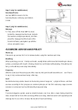
Страница 8: ...ass through handgrip hole and connect with the upright frame Step 3 Insert Safety Tether Insert the safety tether provided into the yellow mark tether hole on the console below the display The treadmi...

Страница 9: ...to release actions and exhale with mouth Inhaling should be coordinated with exhaling If breathing too fast you should stop exercising immediately Frequency After the exercise of the same parts of th...

Страница 10: ...as close as possible with hand keep for 10 15 seconds and then relax Repeat for three times for each leg see picture 2 3 Shank and heel tendon stretching Stand with two hands on the wall or desk and o...

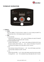
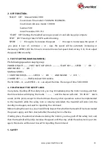
Страница 11: ...fter 5 minutes B Distance Calories model Setting 0 100 minutes or end shows in LCD display and finished it OK Keep Moving If setting 100 0 minutes or end show in LCD display the speed of machine will...

Страница 12: ...TIME window 15 00 twinkle The INCLINE or and SPEED or can adjust the time The range of time 5 00 99 00 4 FUNCTIONS OF THE SAFETY LOCK In any state if pulling off the safety lock you may immediately s...

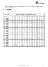
Страница 13: ...www powermaxfitness net 13 In any circumstances remove the safety switch the system is down and sends alarm sound all the windows show 6 ATTACHMENT P1 P12 Program Sports Diagram...

Страница 14: ...y need catch up the running belt and touch the central part of the back of the belt with hand as nearly as possibly If the belt is with silicon resin a bit sense of dampness inside this means no lubri...

Страница 15: ...e not on the centre of running belt If the deviation phenomenon is caused by the uneven force of the user s feet no load rotation for a few minutes can make it normal For deviation phenomenon that can...

Страница 16: ...ult Code Main reason Solution E01 The wire from computer to bottom control board didn t connected well Check the connection wire between computer and control board was well connected Make sure the IC...

Отзывы: