PowerBox Systems Royal SR2 Скачать руководство пользователя страница 16

16

PowerBox-Systems

 − World Leaders in RC Power Supply Systems

You will now see further screen displays which vary according to the data you have 

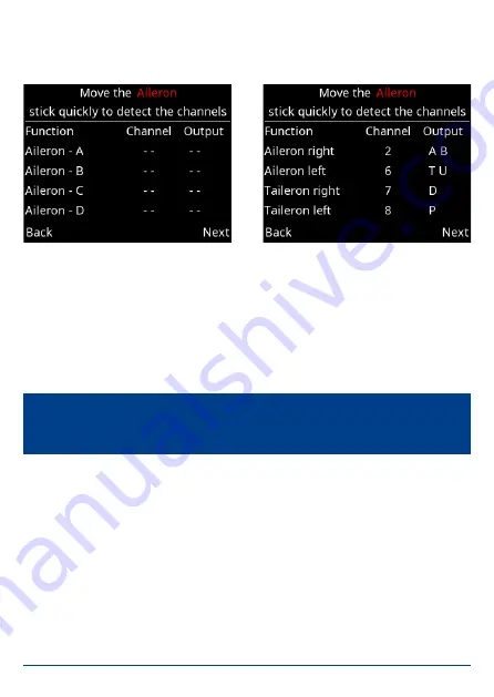
already entered. The following illustrations show the aileron channel as an example, 

based on the above data:

The left-hand picture shows the empty display. Now move the aileron stick at the 

transmitter: the PowerBox checks the input: in this example four channels should 

move.

The right-hand picture shows which channels have been detected, and the outputs 

to which you should connect the servos. Bearing in mind that your individual trans

-

mitter’s channel sequence may not be as shown above, you may need to move the 

transmitter stick briefly and repeatedly until the detected channels appear after the 

appropriate functions.

Repeat the procedure with the elevator and rudder functions. After this you will be 

asked to enter the Gain channel for the iGyro. 

Note: 

If multiple servos are mechanically coupled to a single control surface, 

disconnect the linkage to servos 2 and / or 3, as the servos are not yet matched 

to each other, and you could stall them!

Содержание Royal SR2

Страница 1: ...INSTRUCTION MANUAL 10 2021 PowErBox royAl sr2...

Страница 2: ...x Royal SR2 has four fully independent P BUS interfaces which can be set to two different voltage levels These interfaces can be used to connect servos with an integral P BUS or conven tional servos w...

Страница 3: ...ing the servo matching function and the graphic based menu The final aspect of the system is its pair of integrated door sequencers In addition to a retractable undercarriage it is possible for exampl...

Страница 4: ...NG ON AND OFF 10 4 MAIN MENU 12 5 GENERAL SETTINGS 13 6 SETUP ASSISTENT 14 7 SERVO MATCHING 19 8 DOORSEQUENZER 23 9 OUTPUT MAPPING 29 10 P SERVOBUS 30 11 INPUT MAPPING 33 12 IGYRO 34 13 GYRO SETTINGS...

Страница 5: ...www powerbox systems com 5 royAl sr2...

Страница 6: ...stem detects all transmitter mixers Four selectable output voltages 6 0 V 7 4 V 7 8 V or unregulated Two different voltage levels left and right side separated adjustable Graphic menu diagrams ensure...

Страница 7: ...face travels flight modes Dual Rate Expo etc at the transmitter Using Servo Matching to equalise servos operating in parallel Learning the stick end points in the iGyro menu 2 iGyro set up flight 2 Fi...

Страница 8: ...ers should be spaced well apart inside the model as this increa ses the likelihood that at least one receiver will have good reception at all times even under difficult reception conditions It is perm...

Страница 9: ...sensor list Now select Slot 16 in the sensor list and select PowerBox The telemetry data now appear in Slot 16 or later If a GPS III is connected to the FastTrack input the Competition also delivers...

Страница 10: ...tal rule regarding battery size is that one bat tery on its own should be capable of powering the model reliably If you intend to assemble your own batteries please note that correct polarity is vital...

Страница 11: ...ry type you have selected The supple mentary digital display indicates the exact value The two analogue markers show the current being drawn from the right and left battery The digital current figure...

Страница 12: ...wn above contains the following sub menus iGyro Here you will find all the settings relating to the iGyro These features are only available if an iGyroSAT is connected to the unit Matching If you have...

Страница 13: ...w minutes the primary functions can be ready for use and the Assistant procedure makes it much easier to set up the gyro functions at a later stage 5 GENERAL SETTINGS Before you start using the primar...

Страница 14: ...ccurately Capacity reset channel Enter a channel at this point which you wish to use to reset the consumed battery capacity The capacity is reset when the selected channel is moved to 100 Language Sel...

Страница 15: ...lso using a GPS III as tele metry sensor and for gyro speed compensation this should also be connected to the FastTrack input using a Y lead Select the Assistant widget in the Main Menu and you will s...

Страница 16: ...s which channels have been detected and the outputs to which you should connect the servos Bearing in mind that your individual trans mitter s channel sequence may not be as shown above you may need t...

Страница 17: ...r function you will see a second query regarding the sensitivity of the thrust vector control system This is the method the Assistant uses to set up the basis for a simple but effective method of adju...

Страница 18: ...tablishing the directions of effect sense and learning the transmitter control end points Before you carry out this procedure it is essential to set the direction of effect and the end points of the p...

Страница 19: ...erconnected or which control multiple functions using only a single channel For example the rudder may be coupled to a steerable nosewheel The servo matching procedure is divided up over two screen di...

Страница 20: ...the servo curve at this point using buttons I and II You don t need to use the transmitter to maintain the servo position this makes accurate settings easier Once you have adjusted the curve point to...

Страница 21: ...l stage the servos are strained hard against each other for very brief periods 5 x 100ms We have carried out hundreds of tests with this procedure and have found that it presents no problems to servos...

Страница 22: ...e input channel as the main servo and initialised This means that you do not need to set the assignment of the auxiliaries beforehand in Output Mapping and also do not need to initialise them For exam...

Страница 23: ...drift in use 8 DOORSEQUENZER The Royal SR2 incorporates two independent fully programmable door sequen cers For example Sequencer A can be set up to control the undercarriage and wheel doors while Seq...

Страница 24: ...used to switch the selected sequencer This setting is also present in Input Mapping At the transmitter the switched channel travel should be set to 100 to 100 It is important to know that the door se...

Страница 25: ...si gned to cater for retractable undercarriage sequences Once the Setup Assistant is selected it has to learn a number of fundamental aspects Mode Three modes are available representing different sequ...

Страница 26: ...ngs select Continue The positions of the undercarriage control system and all the wheel doors are now set up in accordance with the number of wheel doors you have entered At this point you should conn...

Страница 27: ...tended position At this point you can check the operation of the sequencer by operating the retract switch on the transmitter If you find a problem perhaps the pause between the undercarriage and the...

Страница 28: ...o change The position of the servo follows the position of the cursor on the line For example if you select a point which stands at 80 the corresponding servo moves slowly to the 80 position To adjust...

Страница 29: ...PPING Output Mapping enables you to assign servo sockets to the transmitter channels and the gyro and sequencer functions All 22 outputs can be assigned and there are no restrictions For ex ample outp...

Страница 30: ...the signal assigned to it The newly developed P ServoBridge is capable of decoding the signals for all ser vos currently available commercially Servos with integral P ServoBus decoding will be availa...

Страница 31: ...e bus assignments separately as was required with the earlier Royal SRS In theory multiple P BUS servos can respond to the same channel but this option makes it impossible to adjust the individual ser...

Страница 32: ...Setup Assistant are designated Aile ron ABCD Elevator ABCD and Rudder ABCD Sequencer A and Sequencer B This function type contains six outputs for each of the door sequencer functions As in the case o...

Страница 33: ...channels coming from the transmitter to functions such as Gyro Sequencer or capacity reset The assignment process is carried out by the Setup Assistant and the Sequencer Assistant If you add functions...

Страница 34: ...he desired channel is selected Press the SET button to confirm your choice 12 IGYRO The iGyro menu provides access to a whole range of Expert settings which enable you to fine tune the iGyro to meet y...

Страница 35: ...cteristic Changing this value hardens and softens the regulatory behaviour of the iGyro If the model appears to respond too abruptly in gusty conditions you should chan ge the value in the direction o...

Страница 36: ...directions shown on the screen to ensure that detection is absolutely reliable move the tail of the model smoothly up and down several times before holding the tail up until the elevators return to n...

Страница 37: ...d an iGyroSAT You must also complete the following points before you start fine tuning the iGyro in flight Settings in the General Settings menu Setup Assistant completed installed orientation learned...

Страница 38: ...first flight it is essential to re learn the stick end points in the Gyro menu The iGyro is now ready for the model s initial set up flight Take the aircraft off with gyro gain set to 0 Hold the model...

Страница 39: ...JR und Hott Receiver redundancy SRS Channels 26 Servo outputs total 26 Servo signal resolution 0 5 s Signal repeat rate 10ms 12ms 14ms 16ms 18ms Gyro modes Heading mode Normal mode Gyro sensor type Ex...

Страница 40: ...40 PowerBox Systems World Leaders in RC Power Supply Systems 16 DIMENSIONS...

Страница 41: ...eceivers Installed orientation can be selected 16 bit processor for fast high resolution signal processing Robust aluminium case GPS III Order No 3525 Features Latest generation of GPS Helix antenna f...

Страница 42: ...will find the forum at the following address www forum powerbox systems com 19 GUARANTEE CONDITIONS At PowerBox Systems we insist on the highest possible quality standards in the development and manuf...

Страница 43: ...not in a position to ensure that you observe our instructions regarding instal lation of the PowerBox Royal SR2 fulfil the recommended conditions when using the unit or maintain the entire radio contr...

Страница 44: ...PowerBox Systems GmbH Ludwig Auer Stra e 5 86609 Donauw rth Germany 49 906 99 99 9 200 49 906 99 99 9 209 www powerbox systems com 10 2021...

Отзывы: