background image

9

Power-Flo Pumps & Systems • 877-24PUMPS • www.powerflopumps.com

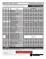
Disassembly & Assembly

Impeller and Volute:

Disconnect power.  Disconnect discharge 

piping. Remove screen (14) by removing 

springs (33) and lifting off.  Remove cap 

screws (29) and pull volute (1) and gasket 

from bearing sleeve (9). Remove set screw 

(3), unscrew counter-clockwise impeller 

(2) from motor shaft. Replace impeller if 

worn or pitted.

Reassemble by placing shims (5) on shaft, 

to ensure proper clearance between 

impeller (2) and bearing sleeve (9). The 

clearance should be approximately .03 

inches. Screw impeller (2) clockwise onto 

shaft and place set screw (3) in place and 

tighten. Place gasket (30) and volute (1) 

onto bearing sleeve (9) and insert cap 

screws in place and tighten. Replace 

screen (14) with springs (33).

IMPORTANT:

For units Dated Jan. 2011 and newer, with 

Ball Bearing Design, continue on.

For unites prior to Jan. 2011 with sleeve 

design, see pages 11 through 14.

Motor & Shaft Seal:

Remove screen, volute and impeller 

as previously stated and drain oil from 

housing. Loosen gland nut (17) and slide 

it back on cord (18). Remove hex nuts 

(20) and lockwashers (21) from studs (28) 

and pull housing end (19) from housing 

tube (27).  Disconnect cord set (18) and 

check for damage or cracks, replace if 

required. Remove grommet (15), friction 

rings (16) from housing end (19), replace 

if damaged. Pull housing tube (27) from 

bearing sleeve (9). Remove seal spacer 

(31) and v-ring (6) from shaft. Loosen 

motor screws and pull bearing sleeve (9) 

with shaft seal (8) from motor. 

IMPORTANT

 that you mark location of 

overload in relation to bearing sleeve 

(9). Remove retaining ring (7) and press 

seal assembly (8) out of bearing sleeve. 

Replace complete seal if seal shows 

signs of uneven wear on seal faces, 

chips, or scratches. If replacing seal, 

remove stationary by prying out with flat 

screwdrive.

Examine o-rings (23) and replace if 

damaged.  Check motor capacitor (12) 

with an Ohm meter by first grounding 

the capacitor by placing a screwdriver 

across both terminals and then removing 

screwdriver.  Connect Ohm meter (set 

on high scale) to terminals.  If needle 

moves to infinity (

) then drifts back, the 

capacitor is good. If needle does not move 

or moves to infinity (

) and does not 

drift back, replace capacitor (12).  Inspect 

motor winding for shorts and check 

resistance values. Check rotor for wear. If 

rotor or the stator windings are defective, 

the complete motor must be replaced. 

To test the overload, check the continuity 

between the black and white wires.

 IMPORTANT! - All parts must be

 clean before reassembly. 

 Handle seal parts with extreme 

 care. DO NOT damage lapped 

 surfaces.

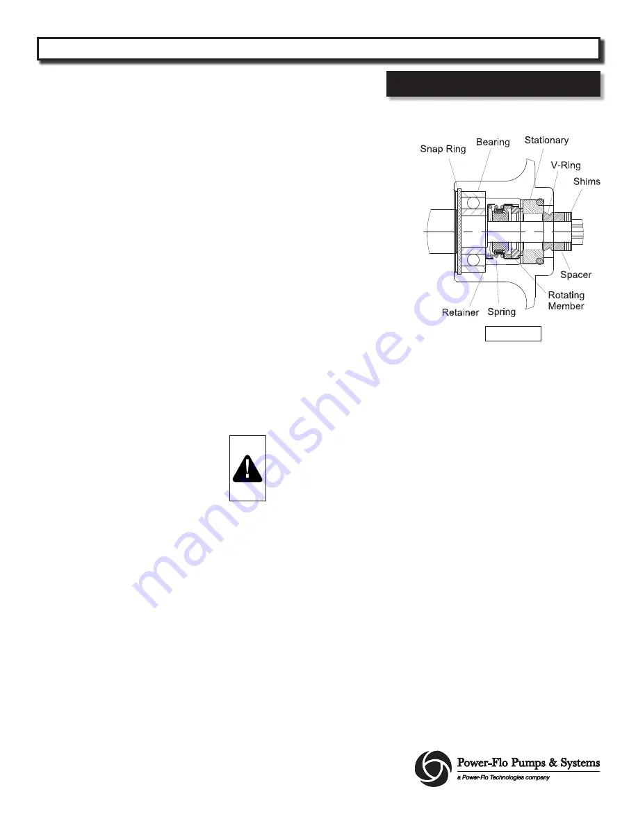
To reassemble, clean seal cavity in bearing 

sleeve (9) and oil. Lightly oil stationary 

member of seal, and with lapped surface 

facing motor, press stationary member 

with seal pusher tool into bearing sleeve 

(9).

Lightly oil 

(Do not use grease)

 inner 

surface of rotating member.  With the 

lapped surface facing inward, place 

rotating member into bearing sleeve (9) 

until it seats against stationary member.

Place the spring and retaining ring onto 

rotating member.  Press bearing (39) into 

bearing sleeve (9) and snap ring (7) into 

bearing sleeve (9).

Lightly oil 

(Do not use grease) 

the shaft 

on motor (10). Assemble bearing sleeve 

(9) onto motor (10), being carfull not to 

damage seal. locate overload as noted (or 

at the 11 o’clock position as viewed from 

motor end), with the four motor bolts. 

Place capacitor (12) into bracket (25) if 

removed and secure with screw. Connect 

flag terminal from motor and terminal 

boot (13) to capacitor (12). 

Place one o-ring (23) into groove on 

bearing sleeve (9) being careful not to 

damage the o-ring. Slide housing tube 

(27) onto bearing sleeve (9). Place o-ring 

(23) into groove on housing end piece 

(19) and place end piece onto housing 

tube (27). Place pump support (22) onto 

lower studs (28) and lockwashers (21) and 

hex nuts (20) onto studs and tighten.

Place v-ring (6) and seal spacer (31) onto 
shaft until seated. Assemble sceen, volute 
and impeller as described.

Service

Figure 1

PFU31, PFU51, PFU71, PFU102, PFU152, PFU202 

     Submersible Fountain Pumps

Содержание PFU102 Series

Страница 1: ...877 24PUMPS www powerflopumps com ISP No PFU_b 1 2021 INSTALLATION SERVICE PARTS MANUAL Series PFU31 PFU51 PFU71 PFU102 PFU152 PFU202 1 3 1 2 3 4 1 1 1 2 2HP 3450 RPM 60 Hz Submersible Fountain Pumps...

Страница 2: ...ye protection when working on pumps Do not wear loose clothing that may become entangled in moving parts Pumps build up heat and pressure during operation Allow time for pumps to cool before handling...

Страница 3: ...ical Carbon Ceramic Buna N POWER CORD 12 Ft MOTOR END BEARING Single Row Ball Oil Lubricated PUMP END BEARING Single Row Ball Oil Lubricated MOTOR Oil Filled Squirrel Cage Induction NEMA B Design Clas...

Страница 4: ...4 Power Flo Pumps Systems 877 24PUMPS www powerflopumps com Dimensions Performance PFU31 PFU51 PFU71 PFU102 Submersible Fountain Pumps...

Страница 5: ...ricated PUMP END BEARING Single Row Ball Oil Lubricated MOTOR Oil Filled Squirrel Cage Induction NEMA B Design Class H Insulation SINGLE PHASE Permanent Split Capacitor PSC Includes Overload Protectio...

Страница 6: ...6 Power Flo Pumps Systems 877 24PUMPS www powerflopumps com Dimensions Performance PFU152 PFU202 Submersible Fountain Pumps...

Страница 7: ...tomatic overload protector and does not require a control box Connect the white and black wires of the motor lead to the two line leads from the power source fused disconnect switch or breaker box Con...

Страница 8: ...ump on it s end remove pipe plug 32 from housing tube 27 Check oil for contamination using an oil tester with a range to 30 Kilovolts breakdown If oil is found to be clean and uncontaminated measuring...

Страница 9: ...nding the capacitor by placing a screwdriver across both terminals and then removing screwdriver Connect Ohm meter set on high scale to terminals If needle moves to in nity then drifts back the capaci...

Страница 10: ...riction ring into housing end piece 19 Apply pipe sealant to gland nut 17 screw into end piece and torque gland nut to 17 5 ft lbs to prevent water leakage Service For Repair Part Please supply Model...

Страница 11: ...pair Parts Bearing Design For Repair Part Please supply Model Number and MFG Date as shown on Name Plate and Part Description and Part Number as shown on Parts List Figure 4 PFU31 PFU51 PFU71 PFU102 P...

Страница 12: ...0 Stainless 21 10 Lockwasher 1 4 22 2 Pump support PF023316 PF023316 PF023316 PF023316 23 2 O ring Buna N PF016068 PF016068 PF016068 PF016068 24 2 Terminal Connector Plastic PF079318 PF079318 PF079318...

Страница 13: ...ockwasher 1 4 22 2 Pump support PF61PFU1503 PF61PFU1503 23 2 O ring Buna N 156 ID x 3 5mm PF63PFU1501 PF63PFU1501 24 2 Terminal Connector Plastic PF079318 PF079318 25 1 Capacitor bracket Steel PF03985...

Страница 14: ...ply Model Number and MFG Date as shown on Name Plate and Part Description and Part Number as shown on Parts List Repair Parts Sleeve Design For Repair Part Please supply Model Number and MFG Date as s...

Страница 15: ...dings are defective the complete motor must be replaced To test the overload check the continuity between the black and white wires Assemble bearing sleeve 9 onto motor 10 locating overload as noted o...

Страница 16: ...m Repair Parts Sleeve Design For Repair Part Please supply Model Number and MFG Date as shown on Name Plate and Part Description and Part Number as shown on Parts List Figure 4 For Units previous to J...

Страница 17: ...F086039 19 1 Housing end Brass PF026850 PF026850 PF026850 PF026850 20 10 Hex nut 1 4 20 Stainless 21 10 Lockwasher 1 4 22 2 Pump support PF023316 PF023316 PF023316 PF023316 23 2 O ring Buna N PF016068...

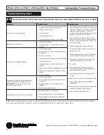
Страница 18: ...quired to eliminate leakage 11 Check pump temperature limits and fluid temperature 12 Replace portion of discharge pipe with flexible connector or tighten existing piping 13 Check screen and or suctio...

Страница 19: ...19 Power Flo Pumps Systems 877 24PUMPS www powerflopumps com PFU31 PFU51 PFU71 PFU102 PFU152 PFU202 Submersible Fountain Pumps Notes...

Страница 20: ...accordance with Manufacturer s installation instructions that has been exposed to outside substances including but not limited to the following sand gravel cement mud tar hydrocarbons hydrocarbonderi...

Отзывы: