background image

2

Power-Flo Pumps & Systems • 877-24PUMPS • www.powerflopumps.com

General Safety Information

® Power-Flo  is a registered trademark of Power-Flo Technologies Inc.

Other brand and product names are trademarks or registered trademarks of their respective holders.

Alteration Rights Reserved.   11/2007 - 7/15, 12/15, 8/17, 9/2020, 1/2021

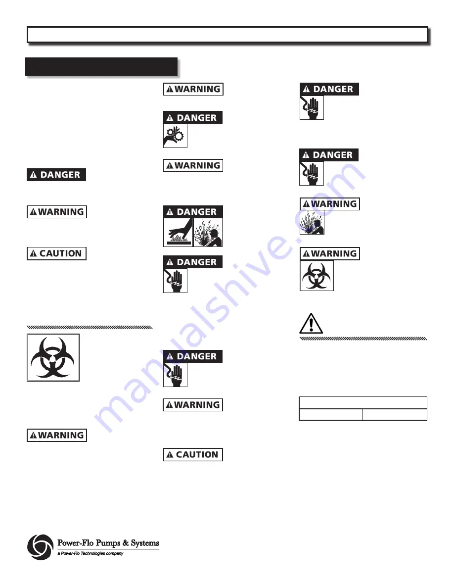
Before installation, read the following 
instructions carefully. Failure to follow 
instruction and Safety information could 
cause serious bodily injury, death and/or 
property damage. Each Power-Flo pump is 
individually factory tested to insure proper 
performance. Closely following these 
instructions will eliminate potential operating 
problems, assuring years of trouble-free 
service.

                                           “

Danger” indicates


        an imminenty 

hazardous situation which, if not avoided, 

WILL result in death or serious injury.

                                                 “Warning” indicates


        an imminenty 

hazardous situation which, if not avoided, 

MAY result in death or serious injury.


        “Caution”  indicates


         an potentially 

hazardous situation which, if not avoided, 

MAY result in minor or moderate injury.

IMPORTANT - Power-Flo Pumps and 

Systems is not responsible for losses, injury 

or death resulting from failure to observe 

these safety precautions, misuse, abuse or 

misapplication of pumps or equipment.

 ALL


RETURNED 

 PRODUCTS MUST BE
 CLEANED, SANITIZED,
 OR RECONTAMINATED

 PRIOR TO SHIPMENT, 

TO INSURE EMPLOYEES 

WILL NOT BE EXPOSED TO HEALTH 
HAZARDS IN HANDLING SAID MATERIAL. 
ALL APPLICABLE LAWS AND REGULATIONS 
SHALL APPLY.


       Installation, wiring,


       and junction 

connections must be in accordance with 
the National Electric Code and all applicable 
state and local codes. Requirements may 
vary depending on usage and location.


        Installation and


        servicing is to be 

conducted by qualified personnel only.


        Keep clear of suction


       and discharge

 openings. 

Do not

 insert fingers in 

 pump with power connected.


       Always wear eye


       protection when 

working on pumps. Do not wear loose 
clothing that may become entangled in 
moving parts


 Pumps build up heat 


      and pressure during

 operation. Allow time

 for pumps to cool 

 before handling or
 servicing. 


      This pump is 

not


      intended for use

 in swimming pools or water 
 installations where human contact
 with pumped fluid. Pumps when 

used as a decorative water fountain pump 
MUST be used  in circuit protected by a 
Ground Fault Interrupter. Installations in 
Decoritive Fountains or Water Features 
provided for visual enjoyment MUST be 
installed per ALL State and Local codes


       Risk of electric shock. 


       To reduce risk of 

  electric shock, always disconnect 
  pump from power source before 
  handling. 

Lock out power & tag.


Do not

 us these 


       pumps in water 

over 145˚F. 

Do not

 exceed manufactures 

recommended maximum performance, as 
this could cause the motor to overheat.


      For cool operations the


      suction chamber keeps 

motor 2/3 submerged at all times.


Do not

 lift, carry or 


      hang pump by the

 electrical cables. Damage to the
 electrical cables can cause shock,
 burnes or death. 

Never

 handle 

connected power cords with wet hands. Use 
appropriate lifting device.


      Failure to permanently


      ground the pump, 

 motor and controls before
 connecting to power can cause
 shock, burns or death.


        These pumps are 

NOT


 to be installed in

 locations classified as hazardous in
 accordance with the National 
 Electric Code, ANSI/NFPA 70.


       Bronze/brass fitted 


       pumps may contain

 levels higher than considered
 safe for potable water systems.
 Government agencies have
  determined that leaded copper 

alloys should not be used in potable water 
applications.

IMPORTANT!

Prior to installation, record Model 

Number, MFG Date, Amps, Voltage, Phase 

and HP, from pump name plate for future 

reference. Also record the Voltage and 

Current Readings at Startup:

1 Phase Models

Amps:

Volts:

Model Number: ____________________

MFG Date: ____________

PHASE: ______ HP: _________________

PFU31, PFU51, PFU71, PFU102, PFU152, PFU202 

     Submersible Fountain Pumps

WARNING: 

CANCER AND REPRODUCTIVE HARM-

WWW.P65WARNINGS.CA.GOV

Содержание PFU102 Series

Страница 1: ...877 24PUMPS www powerflopumps com ISP No PFU_b 1 2021 INSTALLATION SERVICE PARTS MANUAL Series PFU31 PFU51 PFU71 PFU102 PFU152 PFU202 1 3 1 2 3 4 1 1 1 2 2HP 3450 RPM 60 Hz Submersible Fountain Pumps...

Страница 2: ...ye protection when working on pumps Do not wear loose clothing that may become entangled in moving parts Pumps build up heat and pressure during operation Allow time for pumps to cool before handling...

Страница 3: ...ical Carbon Ceramic Buna N POWER CORD 12 Ft MOTOR END BEARING Single Row Ball Oil Lubricated PUMP END BEARING Single Row Ball Oil Lubricated MOTOR Oil Filled Squirrel Cage Induction NEMA B Design Clas...

Страница 4: ...4 Power Flo Pumps Systems 877 24PUMPS www powerflopumps com Dimensions Performance PFU31 PFU51 PFU71 PFU102 Submersible Fountain Pumps...

Страница 5: ...ricated PUMP END BEARING Single Row Ball Oil Lubricated MOTOR Oil Filled Squirrel Cage Induction NEMA B Design Class H Insulation SINGLE PHASE Permanent Split Capacitor PSC Includes Overload Protectio...

Страница 6: ...6 Power Flo Pumps Systems 877 24PUMPS www powerflopumps com Dimensions Performance PFU152 PFU202 Submersible Fountain Pumps...

Страница 7: ...tomatic overload protector and does not require a control box Connect the white and black wires of the motor lead to the two line leads from the power source fused disconnect switch or breaker box Con...

Страница 8: ...ump on it s end remove pipe plug 32 from housing tube 27 Check oil for contamination using an oil tester with a range to 30 Kilovolts breakdown If oil is found to be clean and uncontaminated measuring...

Страница 9: ...nding the capacitor by placing a screwdriver across both terminals and then removing screwdriver Connect Ohm meter set on high scale to terminals If needle moves to in nity then drifts back the capaci...

Страница 10: ...riction ring into housing end piece 19 Apply pipe sealant to gland nut 17 screw into end piece and torque gland nut to 17 5 ft lbs to prevent water leakage Service For Repair Part Please supply Model...

Страница 11: ...pair Parts Bearing Design For Repair Part Please supply Model Number and MFG Date as shown on Name Plate and Part Description and Part Number as shown on Parts List Figure 4 PFU31 PFU51 PFU71 PFU102 P...

Страница 12: ...0 Stainless 21 10 Lockwasher 1 4 22 2 Pump support PF023316 PF023316 PF023316 PF023316 23 2 O ring Buna N PF016068 PF016068 PF016068 PF016068 24 2 Terminal Connector Plastic PF079318 PF079318 PF079318...

Страница 13: ...ockwasher 1 4 22 2 Pump support PF61PFU1503 PF61PFU1503 23 2 O ring Buna N 156 ID x 3 5mm PF63PFU1501 PF63PFU1501 24 2 Terminal Connector Plastic PF079318 PF079318 25 1 Capacitor bracket Steel PF03985...

Страница 14: ...ply Model Number and MFG Date as shown on Name Plate and Part Description and Part Number as shown on Parts List Repair Parts Sleeve Design For Repair Part Please supply Model Number and MFG Date as s...

Страница 15: ...dings are defective the complete motor must be replaced To test the overload check the continuity between the black and white wires Assemble bearing sleeve 9 onto motor 10 locating overload as noted o...

Страница 16: ...m Repair Parts Sleeve Design For Repair Part Please supply Model Number and MFG Date as shown on Name Plate and Part Description and Part Number as shown on Parts List Figure 4 For Units previous to J...

Страница 17: ...F086039 19 1 Housing end Brass PF026850 PF026850 PF026850 PF026850 20 10 Hex nut 1 4 20 Stainless 21 10 Lockwasher 1 4 22 2 Pump support PF023316 PF023316 PF023316 PF023316 23 2 O ring Buna N PF016068...

Страница 18: ...quired to eliminate leakage 11 Check pump temperature limits and fluid temperature 12 Replace portion of discharge pipe with flexible connector or tighten existing piping 13 Check screen and or suctio...

Страница 19: ...19 Power Flo Pumps Systems 877 24PUMPS www powerflopumps com PFU31 PFU51 PFU71 PFU102 PFU152 PFU202 Submersible Fountain Pumps Notes...

Страница 20: ...accordance with Manufacturer s installation instructions that has been exposed to outside substances including but not limited to the following sand gravel cement mud tar hydrocarbons hydrocarbonderi...

Отзывы: