15
Power-Flo Pumps & Systems • 877-24PUMPS • www.powerflopumps.com
PFU31, PFU51, PFU71, PFU102
Submersible Fountain Pumps
Motor & Shaft Seal:
Remove screen, volute and impeller
as previously stated and drain oil from
housing. Loosen gland nut (17) and slide
it back on cord (18). Remove hex nuts
(20) and lockwashers (21) from studs (28)
and pull housing end (19) from housing
tube (27). Disconnect cord set (18) and
check for damage or cracks, replace if
required. Remove grommet (15), friction
rings (16) from housing end (19), replace
if damaged. Pull housing tube (27) from
bearing sleeve (9). Remove seal spacer
(31) and v-ring (6) from shaft. Loosen
motor screws and pull bearing sleeve (9)
with shaft seal (8) from motor.
IMPORTANT
that you mark location of
overload in relation to bearing sleeve (9).
Remove retaining ring (7) and press
seal assembly (8) out of bearing sleeve.
Replace complete seal if seal shows
signs of uneven wear on seal faces,
chips, or scratches. If replacing seal,
remove stationary by prying out with flat
screwdrive.
Examine o-rings (23) and replace if
damaged. Check motor capacitor (12)
with an Ohm meter by first grounding
the capacitor by placing a screwdriver
across both terminals and then removing
screwdriver. Connect Ohm meter (set
on high scale) to terminals. If needle
moves to infinity (
∞
) then drifts back, the
capacitor is good. If needle does not move
or moves to infinity (
∞
) and does not drift
back, replace capacitor (12).
Inspect motor winding for shorts and
check resistance values. Check rotor for
wear. If rotor or the stator windings are
defective, the complete motor must be
replaced. To test the overload, check the
continuity between the black and white
wires.
Assemble bearing sleeve (9) onto motor
(10), locating overload as noted (or at the
11 o’clock position as viewed from motor
end), with the four motor bolts. Place
capacitor (12) into bracket (25) if removed
and secure with screws, Connect flag
terminal from motor and terminal boot
(13) to capacitor (12).
Place one o-ring (23) into groove on
bearing sleeve (9) being careful not to
damage the o-ring. Slide housing tube
(27) onto bearing sleeve (9). Place o-ring
(23) into groove on housing end piece
(19) and place end piece onto housing
tube (27). Place pump support (22) onto
lower studs (28) and lockwashers (21) and
hex nuts (20) onto studs and tighten.
IMPORTANT! - All parts must be
clean before reassembly.
Handle seal parts with extreme
care. DO NOT damage lapped
surfaces.
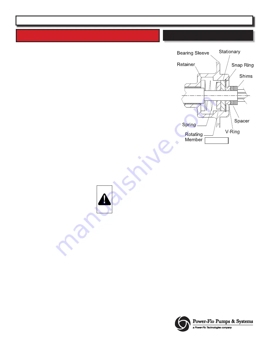
To reassemble, clean seal cavity in bearing
sleeve (9) and oil. Insert seal (8) retaining
ring along with spring onto motor shaft
until seated.
Lightly oil
(Do not use grease)
shaft and
inner surface of rotating member and
assembly tool bullet. Place the bullet
tool over shaft threads and with lapped
surface facing out, press rotating member
with seal pusher tool onto shaft and into
bearing sleeve (9) until it seats against
shoulder of shaft.
Lightly oil
(Do not use grease)
stationary
member of seal, and with lapped surface
facing motor, press stationary member
with seal pusher tool into bearing sleeve
(9) until it seats against rotating member.
Replace retaining ring (7), place v-ring
(6) and seal spacer (31) onto shaft until
seated. Assemble sceen, volute and
impeller as described.
Service - Sleeve Design
For Units previous to Jan. 2011
Figure 1


