8964330
OBD2 Multi-Function Digital Heads Up Display
V4.0
10
For technical questions call 1-800-665-8685
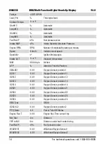
ACC P.B
000.0%
Absolute Throttle Position B
ACC P.C
000.0%
Absolute Throttle Position C
ACC P.D
000.0%
Absolute Throttle Position D
ACC P.E
000.0%
Absolute Throttle Position E
ACC P.F
000.0%
Absolute Throttle Position F
Intake Air Temperature ºC or ºF
Air temperature at the air intake manifold.
LED SETTINGS
The 10 full-colour LEDs (A) above the digital screen are status or an alarm
indicator for the selected instrument field. The LEDs colour, direction and step
interval and alarm can be set in the submenu.
1. Enter the LED Settings submenu (Fig. 11).
2. Edit the MODE field to and use the arrow up and arrow down buttons to
select either ALERT RPM or ALERT SHIFT instrument. Consult Table 2 for
the available instrument alarms.
3. Press the OK button to confirm the selection.
4. Choose the STEP value. There
are four options: 100, 200, 250
or 500 rpm. This is the amount
of RPMs between each LED or
each colour change.
5. Chose to either use the SHOW
MODE or MULTCOLOR for the
method that the LEDs illuminate
to indicate each step.
SHOW MODE
6. Enter the SHOW MODE field to choose the direction for the LEDs to light
up during the step interval. The options are from left to right (
•
→
) or
outside to middle. (
→
•
←
).
7. Enter the chosen STEP interval. One LED will light up per each interval
above the default start limit. The interval is calculated differently based on
which direction you’ve chosen in step 4.
Fig. 11


