


8630196
120 Volt spot Welder
V 4.2
16
For technical questions call 1-800-665-8685
It is apparent that the heat input cannot be greater than the total dissipation rate of the workpiece and the
electrode without having metal expelled from the joint.
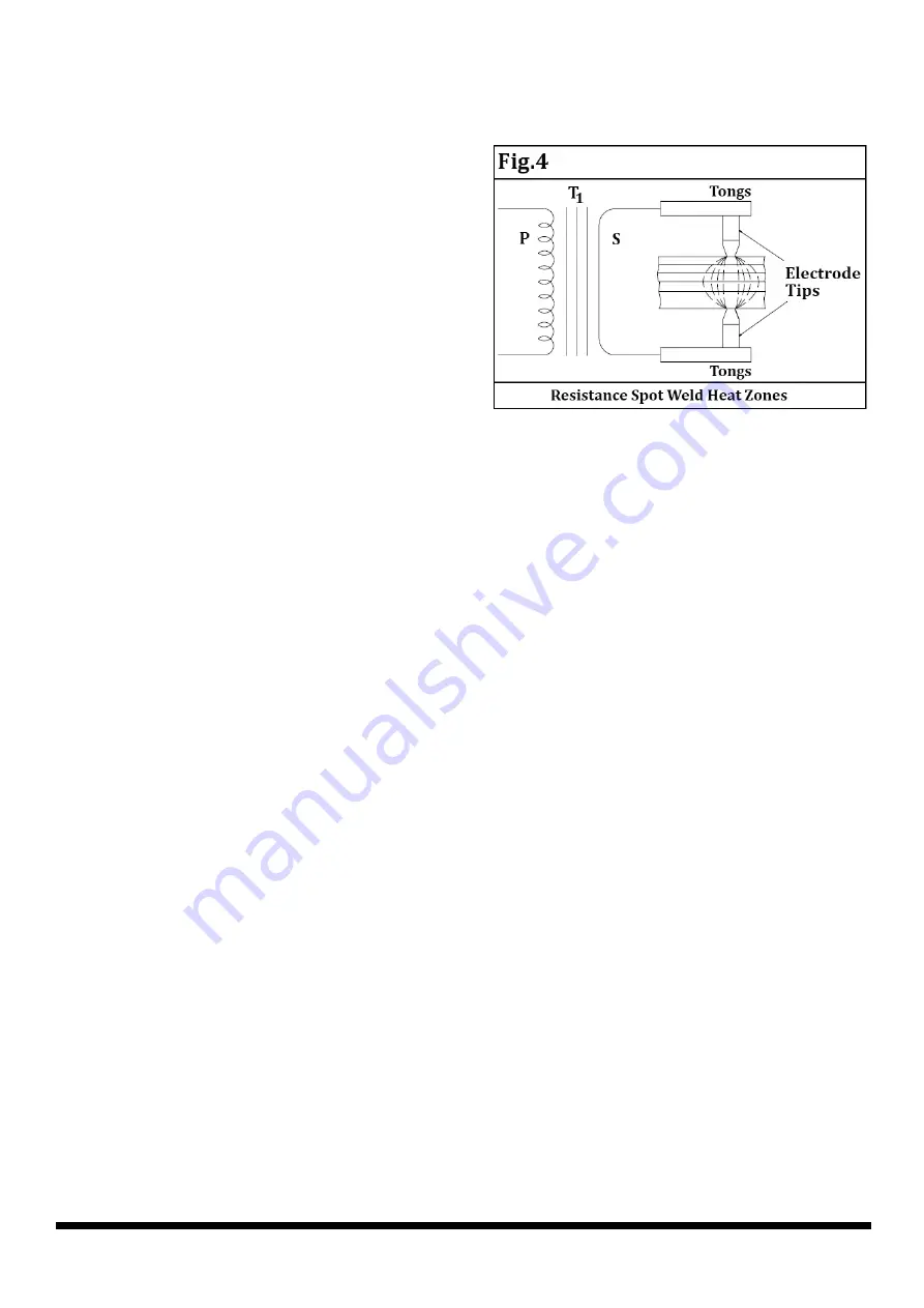
An interesting discovery has been developed recently
concerning the flow of current through the workpiece.
Until recently, current was considered to flow in a
straight line through the weld joint. This is not
necessarily true when multiple thicknesses of material
are being welded. The characteristic is for the current to
“fan out” thereby decreasing the current density at the
point of the weld the greatest distance from the electrode
tips. Figure 4 shows the resistance spot weld heat zones
for several thicknesses of metal. We note that the
uncontrollable variables (such as interface
contamination) are multiplied when resistance spot
welding several thicknesses of material. Quality levels will
be much lower for “stack” resistance spot welding, which explains
why such welding practices are avoided whenever possible.
Disregarding the quality factor, it becomes apparent that the number of thicknesses of a material which may
be successfully resistance spot welded at one time will depend on the material type and thickness as well as
the kVA capacity of the resistance spot welding machine.
kVA rating, duty cycle, and other pertinent information is shown on the resistance spot welding
machine nameplate.
ELECTRODE TIP SIZE
When you consider that it is through the electrode that the welding current is permitted to flow into the
workpiece, it is logical that the size of the electrode tip point controls the size of the resistance spot weld.
Actually, the weld nugget diameter should be slightly less than the diameter of the electrode tip point.
If the electrode tip diameter is too small for the application, the weld nugget will be small and weak. If,
however, the electrode tip diameter is too large, there is danger of overheating the base metal and
developing voids and gas pockets. In either instance, the appearance and quality of the finished weld
would not be acceptable.
To determine the electrode tip diameter will require some decisions on the part of the weldment designer.
The resistance factors involved for different materials will certainly have some bearing on the electrode tip
diameter determination.
NOTE: The tip diameter discussed in this manual refers to the electrode tip diameter at the point of contact
with the workpiece. It does not refer to the major diameter of the total electrode tip.
PRESSURE (WELDING FORCE)
The pressure exerted by the tongs and the electrode tips on the workpiece have a great effect on the amount of
weld current that flows though the joint. The greater the pressure, the higher the welding current value will be,
within the capacity of the resistance spot welding machine.
Setting pressure is relatively easy. Normally, samples of material to be welded are placed between the
electrode tips and checked for adequate pressure to make the weld. The pressure exerted is determined by the
user. If more pressure is required, press down on the handle harder. If less pressure is required, apply less
downward force on the handle. As part of the setting up operation, the tong and electrode tip travel should be
adjusted to the minimum required amount to prevent “hammering” the electrode tips and tip holders.


