background image

Powered by Safety

®

56

Maintenance

01.4IB.51000C

PowlVac® Metal-Clad Switchgear

5kV & 15kV

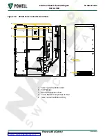
Figure 38  4000A Force Cooled Section Views

a.  Force Cooled Ventilation Exit

b.  Fan Package

c.  Rear Cell Ventilation Duct

d.  Circuit Breaker Compartment Door

e.  Force Cooled Ventilation Entry

a

b

c

d

e

Courtesy of NationalSwitchgear.com

Содержание PowlVac 1200A

Страница 1: ...01 4IB 51000C PowlVac Metal Clad Switchgear 5kV 15kV 1200A 2000A 3000A 4000A Force Cooled Powered by Safety Courtesy of NationalSwitchgear com ...

Страница 2: ...witchgear 5kV 15kV 01 4IB 51000C Contact Information Powell Electrical Systems Inc powellind com info powellind com Service Division PO Box 12818 Houston Texas 77217 2818 Tel 713 944 6900 Fax 713 948 4569 Courtesy of NationalSwitchgear com ...

Страница 3: ...rt symbol is used to address practices not related to personal injury CAUTION NOTICE NOTICE is used to address practices not related to personal injury Qualified Person For the purposes of this manual a qualified person as stated in NFPA 70E is one who has skills and knowledge related to the construction and operation of the electrical equipment and installations and has received safety training t...

Страница 4: ...Powered by Safety PowlVac Metal Clad Switchgear 5kV 15kV 01 4IB 51000C This page left blank intentionally Courtesy of NationalSwitchgear com ...

Страница 5: ... Compartment 7 D Secondary Compartment 8 E Ratings 9 F Lighting Impulse Withstand BIL 9 G Circuit Breakers 10 H Circuit Breaker Racking Mechanism 11 I Safety Interlocks and Provisions 12 1 Key Interlocks 12 2 Circuit Breaker Compartment Safety Provisions 12 J Auxiliary Compartments 13 K Anti Condensation Heaters 13 L Voltage Potential Transformer Rollout Carriage 14 M Fuse Disconnecting Device Rol...

Страница 6: ...Control Cables 32 P Surge Protection 32 Q Roof Entrance Bushing 32 R Bus Duct Entry 33 S Auxiliary Device Rollout Carriage 34 1 Control Power Transformer Rollout 34 2 Fuse Rollout 34 Ch 5 Operation 35 A General 35 B Inserting the Removable Element Into the Compartment 35 1 Inserting the Circuit Breaker Into the Lower Compartment One High Design 36 2 Inserting the Circuit Breaker Into the Upper Com...

Страница 7: ... 51 A General 51 B Overall Maintenance Procedures 51 1 Equipment 52 2 Bus Insulation 52 3 Mechanisms 52 4 Primary Disconnect Device Contacts 52 5 Disconnecting Contacts 52 6 Control Contacts 53 7 Secondary Wiring 53 8 Mechanical Parts 53 9 Ventilation 53 10 Battery and Charging Equipment 53 11 Hardware 53 12 Heaters 53 13 Testing 54 14 Doors 54 15 Interlocks 55 16 Actuators 55 17 4000A Versions On...

Страница 8: ...late Connection 24 Figure 16 Placing the Boot over the Joint 25 Figure 17 Boot Installation 26 Figure 18 Insulation of Bus Bar 27 Figure 19 Single Bus Bar Connection Joint 27 Figure 20 Double Bus Bar Connection Joint 28 Figure 21 Tee Connection Joint 28 Figure 22 Cable Termination Joint 30 Figure 23 Bar Type Current Transformer Joint Insulation 31 Figure 24 Roof Bushing 33 Figure 25 Angle Shipping...

Страница 9: ...int 28 Table H Insulation of Tee Connection Joint 28 Table I Cable Termination Joint 30 Table J Bar Type Current Transformer Joint Insulation 31 Table K Pothead Bushing or Terminator 33 Table L Rated Control Power Voltages Ranges for Circuit Breakers 50 Table M Accessories 58 Table N Lift Trucks 59 Figures Figure 36 Lower Mechanism Operated Cell Switch MOC and Operating Mechanism 47 Figure 37 Uppe...

Страница 10: ...Powered by Safety PowlVac Metal Clad Switchgear 5kV 15kV 01 4IB 51000C This page is intentionally left blank Courtesy of NationalSwitchgear com ...

Страница 11: ...nance or any act requiring the operator to make physical contact with the equipment the power source must be disconnected and the equipment grounded Failure to do so may result in death or serious injury NOTICE The information in this instruction bulletin is not intended to explain all details or variations of the Powell equipment nor to provide for every possible contingency or hazard to be met i...

Страница 12: ...truction details of each particular type of metal clad switchgear The illustrations in this document are provided as general information to aid in showing component locations only All illustrations and photos are shown using deenergized equipment Be sure to follow the appropriate safety precautions while handling any of the equipment Failure to do so may result in death or serious injury WARNING T...

Страница 13: ...c CDR Vacuum Circuit Breaker 01 4IB 60301A PowlVac STD Vacuum Circuit Breaker 01 4IB 60302A PowlVac CDR 63kA Vacuum Circuit Breaker 01 4IB 51056A PowlVac ARM Automatic Racking Mechanism Vacuum Circuit Breaker 01 4IB 51051B Electric Racking Device 51899G10 01 4IB 51808A Vacuum Type Remote Racking Device 51897G29 Courtesy of NationalSwitchgear com ...

Страница 14: ... measurement and test instruments intended for use on electrical systems 1000 V and below 6 Where the possibility of induced voltages or stored electrical energy exists ground the phase conductors or circuit parts before touching them Where it could be reasonably anticipated that the conductors or circuit parts being deenergized could contact other exposed energized conductors or circuit parts app...

Страница 15: ...GEAR WITH THE CONTROL CIRCUIT ENERGIZED 3 EXTREME CARE MUST BE EXERCISED TO KEEP ALL PERSONNEL TOOLS AND OTHER OBJECTS CLEAR OF MECHANISMS WHICH ARE TO BE OPERATED DISCHARGED OR RELEASED These circuit breakers utilize stored energy mechanisms These mechanism must be serviced only by skilled and knowledgeable personnel capable of releasing each spring load in a controlled manner Detailed informatio...

Страница 16: ...lation openings lower unit cable penetrations and view windows The metal clad switchgear is used to protect and control medium voltage alternating current power distribution systems Each unit consists of a number of circuit breaker compartments plus auxiliary compartments containing accessory apparatus The circuit breakers are used to control various types of circuits such as incoming lines bus ti...

Страница 17: ...each compartment located one above the other Note Each construction includes primary and secondary compartments as shown in Figure 2 and 3 These instructions apply to both types of construction Where significant differences exist between the two construction types each is explained separately Figure 3 Two High Basic Construction 1 1 1 8 21 1 2 31 1 2 40 95 1 8 Primary Compartment Secondary Compart...

Страница 18: ... secondary compartments and also between the primary compartments located immediately below or above the secondary compartment A horizontal passageway is provided across the lower rear wall of the compartment with approximately 4 diameter openings provided between all secondary compartments to carry the control and instrumentation wiring between the compartments Additional openings may also be pro...

Страница 19: ... Note If required Field Dielectric Tests should be limited to 75 of Factory Dielectric Test values Direct current dielectric testing is not recommended If DC testing is required see Ch 5 Operation O Test and Inspection for values to be used Table B Ratings of Medium Voltage PowlVac Metal Clad Switchgear 5kV Cell Width inch mm Maximum Voltage Nominal Voltage Power Frequency Withstand kV BIL Crest k...

Страница 20: ...witchgear and as such it has all the necessary interlocks and grounding to interface with the switchgear It is a removable device designed with wheels that make insertion and removal from the compartment a simple operation All circuit breakers with equal ratings are interchangeable For a detailed description of the circuit breaker and its operation refer to the appropriate instruction bulletin for...

Страница 21: ...his time the circuit breaker is in the same physical location as the disconnected position In the connected position the movable primary disconnecting circuits and stationary primary disconnecting circuits are engaged The shutters are open and the secondary circuits and control contacts are completed Interlocks deter the movement of a circuit breaker from one position to another unless the circuit...

Страница 22: ...condition while the circuit breaker is being racked into or out of the connected position Safety shutters open and close over the stationary primary disconnect devices in response to the movement of the circuit breaker racking mechanism A spring discharge interlock is provided to discharge the main closing spring when a circuit breaker is inserted into or withdrawn from the compartment This interl...

Страница 23: ...partments Control power transformer compartments K Anti Condensation Heaters Anti condensation heaters are provided in all PowlVac switchgear in order to facilitate drying and to prevent condensation It is recommended that heaters are energized at all times accordingly no switch or thermostat is provided in the heater circuit unless specified Each one high basic construction is furnished with a he...

Страница 24: ...However these stationary primary disconnects may remain energized Do not remove the rollout tray from its rails without first deenergizing the primary circuit to which the roll out connects Removing the tray makes the stationary primary disconnect devices accessible WARNING Figure 8 Voltage Transformer and Rollout Carriage M Fuse Disconnecting Device Rollout Carriage Current limiting fuses with hi...

Страница 25: ...ted in the compartment behind the rollout carriage These stationary primary disconnect devices may remain energized N Current Transformers Through Type Ring type current transformers Figure 4 c are positioned around the stationary primary disconnect devices These current transformers are removable from the front and may be located on upper and or lower primary disconnect supports When necessary sp...

Страница 26: ...ces on the circuit breaker will engage automatically with the stationary primary disconnect devices near the end of the racking cycle Contact penetration is set by the racking device and no additional adjustments should be necessary The removable element disconnect contacts are self aligning fingers which will compensate for minor misalignment of up to approximately 8 inch Q Lighting For through d...

Страница 27: ...ather The switchgear vertical sections are shipped in an upright position and when received should be kept upright When the switchgear lineup reaches its destination the purchaser should check the material actually received against the shipping list to be sure that all parts have been received If damage is found or suspected file a claim as soon as possible with the transportation company and noti...

Страница 28: ...the elements even for a short period can permanently damage the equipment Space heaters within the equipment should be energized if so equipped Humidity controlling desiccant materials should be utilized when space heaters are not provided or cannot be energized The temperature should be kept above 33 F 1 C and below 140 F 60 C The relative humidity should be kept below 60 or a dew point of 15 C 5...

Страница 29: ...onstruction is shown in Figure 11 The floor channels should have a minimum web dimension of 4 inches The required quantity and location of the floor channels is shown on the drawings furnished with the order The spacing of the floor channels including the center channel must be as shown on the drawings Even though the switchgear is not anchored to the center channel its location is important to th...

Страница 30: ...pace at the front must be sufficient to permit insertion withdrawal and transferring of circuit breakers The space at the rear must be sufficient for installation of cables for inspection and maintenance and on some switchgear to roll out voltage or control power transformers The dimensions shown on the switchgear drawings are those required for proper operation of the switchgear When three or mor...

Страница 31: ... adjacent doors equalized to permit their free swing and present a neat appearance 3 Doors may be raised or lowered vertically moved left or right horizontally or rotated to plumb them by loosening the mounting screws which attach the door to the movable half of the hinge assembly These screws are located on the inside of the door The door assembly may then be adjusted as allowed by the holes in t...

Страница 32: ...cuit Breaker with Shipping Bracket a a Shipping Bracket Figure 14 Auxiliary Device with Shipping Bracket a Shipping Bracket a Before installing or operating a removable element such as the circuit breaker ground and test device or dummy removable element consult the instruction bulletin for directions on installation maintenance and renewal parts for that particular element CAUTION Prior to insert...

Страница 33: ...on to the station grounding system The ground is bolted to the rear of the vertical section near the bottom It is arranged so that connections to the station ground can be made in any unit Where equipment is shipped in more than one group the sections of ground bus must be connected by using the splice plates furnished with the equipment Assemble the ground bus joints as outlined in Ch 4 Installat...

Страница 34: ...ed together For example if three thick copper bars are to be connected the bolt should be 1 long In addition to proper length bolts the bolt assembly must include flat washers split ring lock washers and nuts All hardware must be SAE Grade 5 or better Refer to Figure 15 for proper assembly of hardware Figure 15 Ground Bus Splice Plate Connection a b c d e a Bolt b Flat Washer c Bus Bar d Split Loc...

Страница 35: ...ng bus joints using tape or heat shrink material Applying bus insulating boots 1 Main Bus Joint Insulation Main bus joints are insulated with either a custom fitted boot or with hand applied insulating tape Ch 4 Installation K Main Bus Assembly and Insulation 2 Wrapping of Joints will describe the procedure for hand applied insulating tape wrapped joints After installing main bus conductors the jo...

Страница 36: ...e D Bus Wrapping Components Note All bus bars are to be round edge type b Taped Joints 5kV 15kV i Filler Apply three 3 layers lap of high voltage tape mastic side down at medium tension over all bolt heads nuts bars and splice plates to form a smooth surface for taping Any bars with sharp burrs and edges must be deburred and smoothed before applying tape ii Outerwrap Apply two 2 layers lap of high...

Страница 37: ... 5 8 x 4 x 6 3 8 x 6 x 6 5 8 x 6 600V to 5000V 1 Layer Lap 2 4 5 6 8 9 11 12 4 2 3 3 4 5 5 6 5001V to 15000V 2 Layer Lap 2 9 11 12 18 19 23 24 4 5 6 6 9 10 11 12 Note Apply tape at medium tension to produce a void free uniform build up of tape A medium tension stretches a 0 030 x2 tape down to 0 024 x13 4 and 0 030 x4 down to 0 024 x31 2 Apply with mastic side down Apply 3 layers 1 2 lap for condu...

Страница 38: ...ts HV Tape 0282A3529P005 roll is 030 x 4 x 30 long HV Tape 0282A3529P004 roll is 030 x 2 x 30 long Apply with mastic side down Figure 21 Tee Connection Joint Epoxy Insulation Thermoplastic Sleeving or Tape Insulation 50 12 7 Min 50 12 7 Min A B C C B A Overlap Tape in a Figure Eight Pattern RB Putty Both Ends RB Putty Both Ends 50 12 7 Min A A B B 50 12 7 Min Table H Insulation of Tee Connection J...

Страница 39: ... mechanisms If wiping or vacuuming does not clean the bus adequately only distilled water denatured alcohol or isopropyl alcohol should be used to remove any foreign materials from the insulation surface The use of other solvents may result in severe damage to the insulation system or other parts of the equipment L Primary Cables Access the primary cable connections in PowlVac Metal Clad Switchgea...

Страница 40: ...rapping of joints See Ch 4 Installation K Main Bus Assembly and Insulation 2 Wrapping of Joints Figure 22 Cable Termination Joint Epoxy Insulation Thermoplastic Sleeving or Tape Insulation 50 12 7 Min 6 Cable to Surge Supressors or Lightening Arrestors Potential Transf etc 50 12 7 Min C B A C Table I Cable Termination Joint Insulation Level kV Inner Filler A Outer Wrap B C inches Approx No of Roll...

Страница 41: ...rmers are normally installed in a horizontal position directly above or below the primary cable terminals so that the primary cable or cables can pass through them One transformer is required for each three phase circuit Where armored cable is used the armor must be terminated and grounded before the cable passes through the transformer Armor clamps are furnished for this purpose when specified Wh...

Страница 42: ...void excessive voltage drop when the circuit breakers are operated Where units have been split for shipment any control or other secondary leads that must connect across the split will be arranged with terminal blocks in a convenient location so that the wires can be reconnected The wires will be cut to length and formed before being folded back so that a minimum time will be required for reconnec...

Страница 43: ...nt of the insulation on the flat surfaces Figure 24 Roof Bushing C 75 19 1 Min A B RB Putty Wrap Over First Skirt Only C C 75 19 1 Min B B C A RB Putty Wrap Over First Skirt Only POTHEAD BUSHING TERMINATOR A Table K Pothead Bushing or Terminator Insulation Level kV Inner Filler A Outer Wrap B C inches Approx No of Rolls per Joint of HV Tape 2 or 3 Bars 4 or 6 Bars 5 or 15 RB Putty 3 Layers HV Tape...

Страница 44: ...To close the carriage operate the secondary circuit breaker to the off position lower the interlock slider and turn the T handle counterclockwise It should not be possible to close the secondary circuit breaker with the interlock in this position Close the carriage in a smooth but brisk motion and turn the T handle clockwise raising the interlock slider and operate the secondary circuit breaker to...

Страница 45: ...re disconnected and the control circuits are completed B Inserting the Removable Element Into the Compartment Before inserting the circuit breaker into the compartment be sure that the racking crank arms of the circuit breaker are in the fully withdrawn position pointing towards the moveable primary disconnects Otherwise the primary disconnects shutters or the racking mechanisms may be damaged CAU...

Страница 46: ...m the compartment Note This is the disconnected position 2 Inserting the Circuit Breaker Into the Upper Compartment Two High Design Use the appropriate circuit breaker or ground and test device instruction bulletin in conjunction with this section to insert remove the element from the switchgear compartment NOTICE a Verify that the circuit breaker open closed indicator displays BREAKER OPEN and if...

Страница 47: ...en removing the circuit breaker from the lift truck hold the lift truck firmly in place to prevent the truck from rolling away from the circuit breaker CAUTION C Racking Mechanism The racking mechanism consists of two slotted cam plates mounted on each side of the compartment Figure 36 c and the racking mechanism on the circuit breaker The crank arm rollers at the ends of the racking crank arms of...

Страница 48: ... Circuit Breaker to Upper Cell a Lift Truck Ready to receive the Circuit Breaker d Lift Truck and Switchgear Position b Circuit Breaker placed on the Lift Truck e Circuit Breaker approaching hook c Circuit Breaker latched in the Lift Truck tray f Circuit Breaker rolled into the compartment Courtesy of NationalSwitchgear com ...

Страница 49: ...lock is unlocked and in the opened position Otherwise the racking mechanism may be damaged CAUTION With the three optional methods of racking the front door of the compartment has an opening which enables the racking procedure to be performed This opening is covered by a teardrop cover which automatically closes by gravity when the racking handle is removed The metal clad switchgear door is also p...

Страница 50: ...nt door and align the wheels with the floor pan channels of the compartment Verify that the floor pan channels are free of debris prior to inserting the circuit breaker c Roll the circuit breaker in the compartment until the racking crank arms make contact with the vertical slots in the compartment The anti rollout latch on the lower right side of the circuit breaker will engage the block in the c...

Страница 51: ...e circuit breaker begins to move toward the stationary primary disconnecting devices When the movable primary disconnecting devices of the circuit breaker engage the stationary primary disconnecting devices of the compartment the force required to rotate the racking handle will increase appreciably This force will decrease as the primary disconnecting devices spread and engage fully Continuing rot...

Страница 52: ... compartment make sure the circuit breaker is in the open position and all springs are discharged CAUTION a Verify that the circuit breaker open closed indicator displays BREAKER OPEN If CLOSED close door and open breaker from a remote location or alternately by using the circuit breaker control switch on compartment door Open door and verify that the circuit breaker open closed indicator displays...

Страница 53: ...onnect latch Figure 28 d and remove the circuit breaker compartment secondary disconnect plug Figure 28 c Store the plug so it will not be damaged while withdrawing the circuit breaker Note Removing the secondary disconnect plug will trip a closed breaker and discharge the main closing spring c Press the anti rollout latch Figure 32 a to release the circuit breaker and pull the circuit breaker out...

Страница 54: ... that the circuit breaker is open and a red light indicates that the circuit breaker is closed For the DC control schemes the red light is also arranged to supervise the trip coil and indicate that the trip coil circuit has continuity G Shutters Metal shutters Figure 33 a cover the primary disconnect contacts when the removable element is withdrawn from the compartment Figure 33 Shutters a a Shutt...

Страница 55: ...es of the steel plate When the first variety is used it blocks the operation of the key interlock when a removable element is in the connected position This prevents locking the removable element in the connected position giving the interlock a lock out only function The second variety of steel plate enables the interlock to be operated with the removable element in either the connected or disconn...

Страница 56: ...ism The MOC switch operating arm which projects from the jackshaft of the circuit breaker at the lower left side of the circuit breaker operates in conjunction with the MOC assembly This arm rides over an angle pivoted on the lower left side sheet of the compartment When the circuit breaker is closed the arm moves downward deflecting the angle A linkage to the switch connects the angle and the ass...

Страница 57: ...the test position 3 The secondary disconnect plug may be withdrawn with the circuit breaker in the test position by depressing the secondary disconnect guide which holds the plug in place and pulling straight out on the plug s handle to disconnect the secondary disconnect plug The circuit breaker cannot be operated or racked in either direction with the plug withdrawn Removing the plug will open a...

Страница 58: ...position it connects the upper set of the metal clad switchgear primary disconnect devices to the lower set Under no conditions may the dummy element be racked in or out when the circuit it is connected to is under load This action could result in death or serious injury WARNING Key interlocks are applied to ensure that all source of power is disconnected before operating the dummy removable eleme...

Страница 59: ... be disconnected and the equipment grounded Failure to do so may result in death or serious injury WARNING After the equipment has been installed and all connections made it should be tested and inspected before putting in service Although the equipment and devices have been completely tested at the factory a final field test should be made to ensure that the equipment has been properly installed ...

Страница 60: ... or installation After the switchgear has been installed and all connections to the apparatus it is to control have been made it should be given a final check and test before being energized The connections to the equipment apart from the switchgear such as instrument transformers remote control and interlock circuits and auxiliary switches should be checked for continuity and phase relationship T...

Страница 61: ... maintenance interval should be compared to note any significant changes in the condition of the switchgear When performing maintenance the power source must be disconnected and the equipment grounded Failure to do so may result in death or serious injury WARNING The primary circuits of metal clad switchgear are insulated in order to reduce the size of the equipment However this insulation in most...

Страница 62: ... dirt or other foreign matter from the insulation with a clean cloth saturated with only denatured or isopropyl alcohol Inhalation of vapor could result in minor or moderate injury CAUTION Use only the cleaners recommended in this document Failure to do so could result in equipment damage CAUTION 3 Mechanisms Clean the mechanisms and lubricate wear points The application of lubricants should be he...

Страница 63: ...e of ventilating air should be cleaned of leaves and other possible debris Replace or clean dirty filters 10 Battery and Charging Equipment The control battery is such an important accessary to the switchgear operation that it must be given special periodic attention if it is to have a long life of reliable service Periodic inspections and test are recommended in the battery supplier s instruction...

Страница 64: ...ase insulation resistance readings This variation in insulation resistance between different switchgear lineups emphasizes the value of a series of readings that can be charted to establish a normal insulation level so that progressive weakening of the insulation can be recognized Voltage transformers and control power transformers should be disconnected during these tests as they may not be able ...

Страница 65: ...d up b Clean any dust build up on the forced cooled ventilation exit Figure 38 a and fan package Figure 38 b c Confirm fan operation and proper signal from the alarm switches C Abnormal Conditions Local conditions such as high ambient temperature high humidity salt laden atmosphere corrosive gases heavy dust ash severe circuit operating conditions vermin or insect problems are considered to be abn...

Страница 66: ...tal Clad Switchgear 5kV 15kV Figure 38 4000A Force Cooled Section Views a Force Cooled Ventilation Exit b Fan Package c Rear Cell Ventilation Duct d Circuit Breaker Compartment Door e Force Cooled Ventilation Entry a b c d e Courtesy of NationalSwitchgear com ...

Страница 67: ... B Recommended Renewal Parts A sufficient amount of renewal parts should be stored to enable the prompt replacement of any worn broken or damaged part A sufficient amount of stocked parts minimizes service interruptions caused by breakdowns and saves time and expense When continuous operation is a primary consideration a larger quantity of renewal parts should be stocked depending on the severity ...

Страница 68: ... Closed Door Racking Secondary Disconnect Override Device 51555G01 51555G03 1 Manual Charging Handle 50235P01 50235P01 1 Racking Handle 50218G01 50218G01 1 Racking Start Extension 51066G01 n a 1 CPT Secondary Disconnect 90421G01P 90421G01P 1 PT Secondary Disconnect 90422G01P 90422G01P 1 Umbilical Cord 51702G01 51702G08 1 n a 51702G11 57 PowlVac Lubrication Kit Powlube 104 Powlube 104 1 Courtesy of...

Страница 69: ...ay height 71 inches 68 1 2 inch turning aisle 42 inch entry door access aisle 46040G03 PowlVac and PowlVac AR two high switchgear ARG ASD CDA CDR GCB STD circuit breakers Lowers completely to the floor Maximum tray height 71 inches This lift truck will not accommodate ARM Circuit Breakers or an electrically operated G T 60 inch turning aisle 42 inch entry door access aisle 46040G01 Identical to li...

Страница 70: ...Box 12818 Houston TX 77217 Tel 713 944 6900 Fax 713 948 4569 powellind com info powellind com 2006 Powell Industries Inc All rights reserved 5kV 15kV 1200A 2000A 3000A 4000A Force Cooled 01 4IB 51000C PowlVac Metal Clad Switchgear August 2015 Courtesy of NationalSwitchgear com ...

Отзывы: