Powered by Safety
®
48
Operation
01.4IB.51000C
PowlVac® Metal-Clad Switchgear
5kV & 15kV
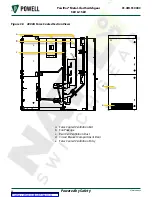
Figure 37 Upper Mechanism-Operated
Cell Switch (MOC) and Operating
Mechanism
a
b
f
c
d
e
a. Mechanism-Operated Cell Switch (MOC)
b. MOC Operating Linkage
c. Cam Plate
d. Shutter Operating Cam Plate
e. Pivoted MOC Operating Angle
f. Bolted-on Angle
m. D
ummy
r
emovABle
e
lement
Dummy removable elements are used as a
means of isolating circuits or bus sections,
where operation is infrequent and a circuit
breaker cannot be economically justified. The
element consists of a framework, and primary
disconnects which simulates the circuit
breaker removable element. The front ends
of the primary disconnects are connected,
top to bottom, by copper bars, which are
fully isolated. The stationary structure is the
same as for the circuit breaker, except that no
secondary disconnect device or control devices
are provided. When the element is racked into
position, it connects the upper set of the
metal-clad switchgear primary disconnect
devices to the lower set.
Under no conditions may the dummy element
be racked in or out when the circuit it is
connected to is under load. This action could
result in death or serious injury.
!
WARNING
Key interlocks are applied to ensure that
all source of power is disconnected before
operating the dummy removable element. The
key interlock used is similar to that described
in
, and is set up for the “Lock in
and out” mode of operation.
The interference plates provided on the
dummy removable element will deter the
insertion of an element of lower
continuous current rating in a
higher-rated compartment. Further, these
plates deter the insertion of any dummy
removable element into any circuit breaker
compartment. It may be possible to insert
a circuit breaker removable element into a
dummy removable compartment as far as the
disconnect position, but it cannot be racked
into the compartment because there is no
secondary disconnect devices to perform the
necessary interlock functions.


