Powered by Safety
®
20
Installation
01.4IB.51000C
PowlVac® Metal-Clad Switchgear
5kV & 15kV
Encircling loops of reinforcing or building
steel around single-phase conductors should
be avoided in the areas for main cables when
these circuits are rated at 600 amperes or
above.
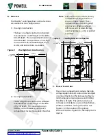
The recommended practice is to weld the
switchgear structure to the floor channels,
using a tack weld at points indicated for
anchoring on the drawing. After welding, any
damaged paint should be removed, and the
weld and surrounding metal should be painted
to deter corrosion. If welding facilities are not
available, the switchgear should be bolted to
the floor channels.
Figure 11 Recommended Floor
Finished Floor Line
Finished Floor Line
Recommended Method
Recommended Method
Door
Door
Floor Channels
Floor Channels
f. p
oSItIonInG
the
m
etAl
-c
lAD
S
WItchGeAr
1) Drawings and Diagrams
Before any installation work is done,
consult and study all drawings and the Bill
of Materials furnished by Powell for the
particular order. The drawings include
arrangement drawings and wiring and
schematic diagrams.
The recommended aisle space for the
front and at the rear of the metal-clad
switchgear is shown on the floor plan
drawing furnished for the particular order.
The space at the front must be sufficient
to permit insertion, withdrawal, and
transferring of circuit breakers. The space
at the rear must be sufficient for installation
of cables, for inspection and maintenance,
and on some switchgear to roll out
voltage or control power transformers.
The dimensions shown on the switchgear
drawings are those required for proper
operation of the switchgear.
When three or more switchgear units are
to be arranged in one continuous line-up,
the center shipping unit should be the first
located. The other shipping line-ups should
then be installed in successive order in each
direction from the center of the structure.
When installing a unit substation or power
center, the power transformer and the
adjacent metal-clad switchgear line-up
should first be lined up and set in position
in accordance with the dimensions on the
base plan drawing for the installation. The
additional units should then be installed.
Establish a base line located a few inches
in front of the units and parallel with the
desired front of the structure. Equalize the
distances from the front of the units to the
base line to make the face of the group
parallel to the base line.
Applicable national or local codes or
regulations may require greater aisle
space than is needed for operation of the
switchgear. It is the purchaser’s responsibility
to comply with these codes and regulations.
NOTICE


