Powered by Safety
®
8
Equipment Description
PowlVac® ARG & ARM Series 4 Vacuum Circuit Breakers
5kV & 15kV - 1200A, 2000A, & 3000A - 25kA, 36kA, 50kA, & 63kA
01.4IB.60306
Ch 3 Equipment Description
A. G
enerAl
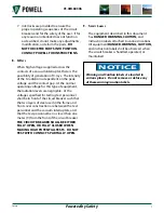
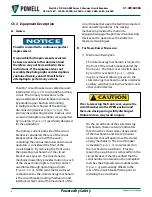
NOTICE
Powell is committed to continuous product
improvement.
It is possible that improvements occurred
between revisions to this document and
therefore, may not be described in these
instructions. If the equipment does not
resemble the photographs and descriptions
contained herein, contact Powell before
attempting to perform any actions.
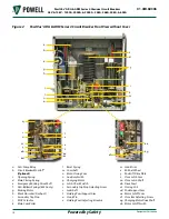
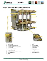
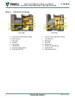
PowlVac® circuit breakers use sealed vacuum
interrupters (
) to control the primary
circuit. The primary connections to the
associated metal-clad switchgear are made
by parallel copper busbars terminating
in multiple contact fingers of the primary
disconnecting devices (
). The
primary disconnecting devices, busbars, and
vacuum interrupter assemblies are supported
by insulators (
) specifically designed
for the application.
The primary current path side of the circuit
breaker is considered the rear of the circuit
breaker, while the side with the cover
containing the various indicators and manual
operators is considered the front of the
circuit breaker. By removing the front cover,
the operating mechanisms of the circuit
breaker are exposed. The stored energy
mechanism assembly provides motion to each
of the vacuum interrupters, moving contact
assemblies through operating pushrods
(
). In the same metal enclosed
compartment as the stored energy mechanism
is the circuit breaker racking mechanism and
interlocks which control the movement of the
circuit breaker between the test/disconnected
and connected positions. The racking
mechanism provides the motion to
engage/disengage the primary disconnecting
devices and to open/close the shutters in
metal-clad switchgear.
B. t
he
S
toreD
e
nerGy
M
echAnISM
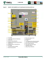
1) Mechanical Description
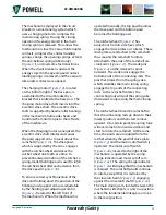
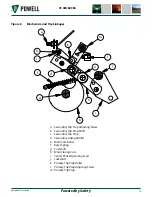
The stored energy mechanism is located in
the front of the circuit breaker behind the
front cover. The front cover is held in place
by ten (10) cover bolts (
) that
may be removed, allowing access to the
stored energy mechanism and its interlocks,
auxiliary switches, racking mechanism, and
other control devices.
!
CAUTION
Prior to removing the front cover, ensure the
circuit breaker is in the OPEN position and
the main closing spring is fully discharged.
Failure to do so may result in injury.
On the escutcheon of the stored energy
mechanism, there are two (2) indicators
that show the various states of operation
of the mechanism and two (2) manual
operators that will open/close the stored
energy mechanism. The circuit breaker
nameplate (
) is also located on
the mechanism escutcheon. If for any
reason the escutcheon is removed from the
circuit breaker, it shall be verified that the
serial number contained on the nameplate
matches the engraved serial number plate
) permanently affixed to the
rear of the circuit breaker frame prior to
installing the escutcheon.


