Powered by Safety
®
20
Equipment Description
PowlVac® ARG & ARM Series 4 Vacuum Circuit Breakers
5kV & 15kV - 1200A, 2000A, & 3000A - 25kA, 36kA, 50kA, & 63kA
01.4IB.60306
e. Control Circuit
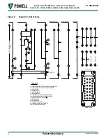
The typical electrical control scheme is
shown in
.
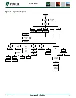
The sequence of operation for all
control schemes is shown in
. Circuit breaker mounted
auxiliary contacts not used in the
control circuit are brought out for
control and indication functions. The
metal-clad switchgear equipment
may provide a circuit breaker MOC
(Mechanism Operated Cell Switch) for
additional contacts.
c. A
utoMAtIc
r
AckInG
M
echAnISM
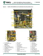
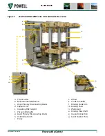
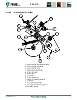
The racking mechanism is the mechanical
assembly that facilitates moving the circuit
breaker between the breaker
test/disconnected and the connected positions
in the circuit breaker compartment. The
main racking mechanism components for the
PowlVac® ARG & ARM Series 4 circuit breakers
are described in the following sections:
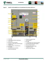
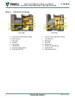
1) Breaker Position Indicator
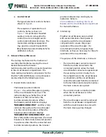
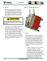
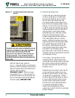
The breaker position indicator
(
) is visible through an opening
in the circuit breaker front cover. The
indicator displays whether the circuit
breaker is in the connected or the
test/disconnected positions. When
the breaker position indicator displays
“BREAKER CONNECTED”, and this is fully
visible in the aperture, the circuit breaker
is in the connected position. When the
breaker position indicator displays
“BREAKER TEST/DISCONNECTED”, and
this is fully visible in the aperture, the circuit
breaker is in the test/disconnected position.
In positions other than the connected and
test/disconnected positions, the breaker
position indicator does not display an
indication. Refer to
Ch 4 Installation, E. Inserting the Circuit
Breaker into the Circuit Breaker Compartment
for more information.
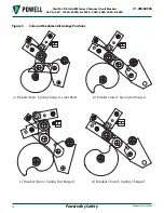
2) Interlocking
PowlVac circuit breakers are provided
with several interlocks that operate in
conjunction with the circuit breaker
compartment to ensure the proper
operation of the circuit breaker. Do
not attempt to modify or bypass these
interlocks, as they are necessary for the safe
operation of the circuit breaker.
The purpose of the interlocks is to ensure:
• The circuit breaker cannot be moved
from the test/disconnected to the
connected position unless the main
circuit breaker contacts are opened and
the secondary control circuitry from
the compartment to the circuit breaker
is completed, and the circuit breaker
cannot be removed from the connected
to the test/disconnected position unless
the main contacts are opened.
• The control circuits cannot be broken
when the circuit breaker is in the
connected position.
• The circuit breaker cannot be removed
from the circuit breaker compartment
with the circuit breaker closed or with
the main closing spring charged.


