27
FAULT FINDING – DIAGNOSTIC DISPLAY – Page 27
DIGITAL DISPLAY
This boiler is fitted with a single digit display which is located
in the front control box behind the hinged door.
The display on which up to 30 different characters can be
illuminated performs two functions.
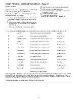
1.
By displaying the following characters provides the user
with a visual indication of the current boiler operating
status.
Power supply switched on but waiting a call for heat
from secondary controls or boiler control switch is in
the “O” position.
Boiler operating, low flow temperature selected.
Boiler operating, high flow temperature selected.
Boiler operating but up to temperature.
Boiler restart delayed to prevent rapid cycling (max
delay time 5 mins).
Pump over run is operating.
FLASHING. Boiler at lockout.
DISPLAY NOT ILLUMINATED – all power off.
2.
By displaying the following characters it will assist the service engineer by working as a fault diagnosing system.
Sensor
Flow or return sensor out of calibration
See chart
Flow sensor
Flow sensor is incorrectly fitted
Check sensor
Case temperature
Temperature within boiler casing too high
See chart
Dry fire
Boiler has been fired without water
Check system
Flow sensor
Sensor failed open or closed circuit
Replace sensor
Return sensor
Sensor failed open or closed circuit
Replace sensor
Case sensor
Sensor failed open or closed circuit
Replace sensor
Dry fire sensor
Sensor failed open or closed circuit
Replace sensor
Fan speed
Fan speed incorrect
See chart
Shorted signal
Flame signal shorted to ground
Check igniter etc
Flame loss
Flame loss after initial detection
See chart
Control failed
Control has failed
Replace control
Wiring fault
Live on neutral connection
Correct fault
Preliminary Test Diagnostics
All boilers are fully tested before leaving the factory, therefore, if an electrical problem is experienced it is very likely that this
is caused by faulty external wiring. If a problem exists disconnect all site wiring from the boiler. Connect a direct fused
electrical supply to boiler terminals L, SwL, N and E and pump live to terminal marked pump L, taking a temporary neutral
and earth connection for the pump from the boiler terminal block.
If boiler now operates correctly, site wiring should be further investigated.
Содержание envoy 30
Страница 4: ...4 TECHNICAL DATA PAGE 4 FIG 2 GENERAL ARRANGEMENT ...
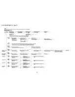
Страница 28: ...28 FAULT FINDING CHART 1 Page 28 ...
Страница 29: ...29 FAULT FINDING CHART 2 Page 29 ...
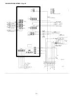
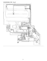
Страница 30: ...30 BOILER INTERNAL WIRING Page 30 ...
Страница 31: ...31 BOILER WIRING LAYOUT Page 31 ...
Страница 36: ...36 Back Page ...

