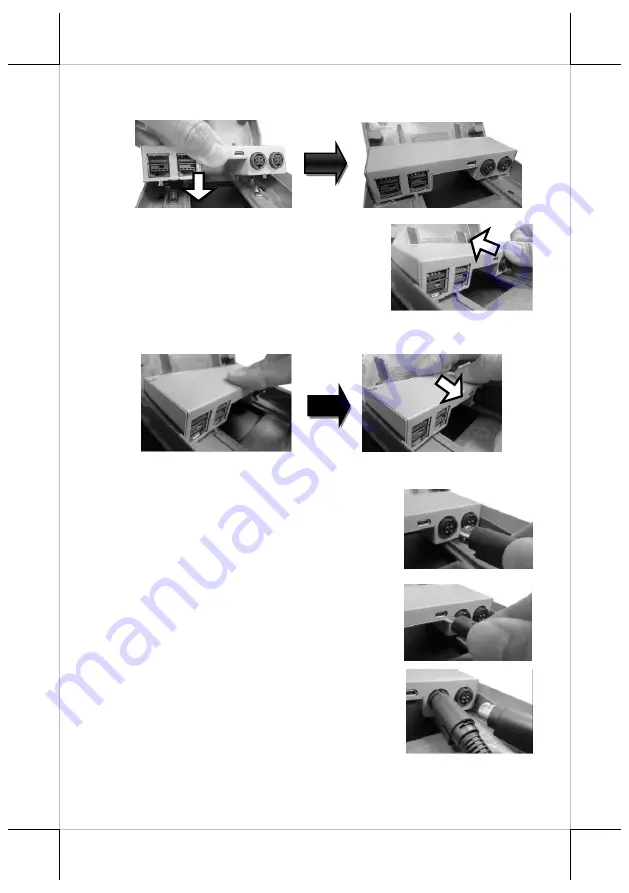
POSIFLEX RT-1016A Скачать руководство пользователя страница 11


11 


3.


Align the two screw bolts at the bottom of PoweredUSB or USB hub 
with rail slots in the base.  


4.


Push PoweredUSB or USB hub in the 
direction shown by the arrow to lock it 
into place. 


To remove the PoweredUSB or USB hub from the rail slots, press 
down the hubs first and then push it outwards. 


5.


Install power adaptor extension cable, USB cable, and power adaptor 
for 

PoweredUSB hub

5.1


Insert one end of the provided power 
adaptor extension cable to DC Input port 
of PoweredUSB hub and another end to 
DC-in power jack of the terminal. 


5.2


Insert mini-USB connector of the USB 
cable to PoweredUSB hub and another 
end to USB3.0 port of the terminal. 


5.3


Connect the connector of the power 
adapter to DC Output port of 
PoweredUSB hub, and the other end to the 
electrical outlet. 


Содержание RT-1016A

Страница 1: ...1 Package Contents RT 1016A 15 6 fanless touch terminal x1 Power adapter x1 Power cord x1 User manual x1 RT 1016A Fanless Touch POS Terminal User Manual 16950903030 Ver C0 http www posiflex com...

Страница 2: ...ce that may cause undesired operation CE CLASS A WARNING This equipment is compliant with Class A of CISPR 32 In a residential environment this equipment may cause radio interference AVERTISSEMENT CE...

Страница 3: ...explosion or the leakage of flammable liquid or gas A battery subjected to extremely low air pressure that may result in an explosion or the leakage of flammable liquid or gas BATTERIE ATTENTION NOTES...

Страница 4: ...4 Views of RT 1016A Front View Rear View Bottom View P Cap Touch Panel LED indicator Camera Optional...

Страница 5: ...terminal immediately and power off the RT terminal When the AC power is turned off if the UPS battery is very low the RB 5000 will beep once every second At this moment power off the RT terminal immed...

Страница 6: ...re Please do NOT press on the LCD panel while setting up the tilt angle Installing Power Adapter and Cables The following provides instructions required to install your cables 1 Lay the terminal with...

Страница 7: ...nd then pulling the cover outwards 3 To remove the stand cover from the base grab the top side of the cover 1 lift the stand cover up gently 2 pull it at a 45 degree angle and then 3 slide it in the h...

Страница 8: ...n be held into place and passed through the cable exit after sliding back the stand cover 7 7 1 Place back the sytem back cover Make sure it is well locked into place with a click sound 7 2 For the fi...

Страница 9: ...endommager les c bles ce qui est consid r comme un dommage artificiel et n est pas couvert par la garantie Le cordon d alimentation doit tre connect une prise de courant avec mise la terre Installing...

Страница 10: ...ion of PoweredUSB or USB hub 1 After tilting the screen all the way down remove the system back cover 1 1 If the system back cover is fire resistant first locate the screw as indicated in the figure a...

Страница 11: ...utwards 5 Install power adaptor extension cable USB cable and power adaptor for PoweredUSB hub 5 1 Insert one end of the provided power adaptor extension cable to DC Input port of PoweredUSB hub and a...

Страница 12: ...ire resistant system back cover please insert another screw into the screw hole indicated in the figure and secure it Status LED Indicator LED status indicator which is located at the bottom edge of t...

Страница 13: ...y from other devices to ensure the machine is properly cooled down and functioning normally Specifications RT 1016A CPU Rockchip RK3399 System Memory 2GB 4GB onboard Storage Device 16GB 32GB 64GB eMMC...

Страница 14: ...SB port attachment for RT series RA 104 2D scanner attachment for RT series RA 301 3 in 1 MSR Fingerprint Sensor 2D scanner attachment for RT series LM TM 4010 9 7 2nd display for RT series terminal L...

Страница 15: ...15 MEMO...

Страница 16: ...16 MEMO...

Отзывы: