HT-4600/PB-4600 series Technical Manual 52
up from the main system unit with a ribbon cable in connection. Please find the
connector removal strap from inside the bottom of the LCD assembly. Disconnect this
cable by pulling at the strap.
Don’t ever pull the cable itself.
Then you can take the
LCD assembly aside and put it in a place safe from any scratch or damage.
INSIDE LCD PANEL ASSEMBLY
If not for working on either the LCD panel or the touch panel,
the disassembly of display screen is not required and this
section can be skipped.
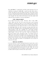
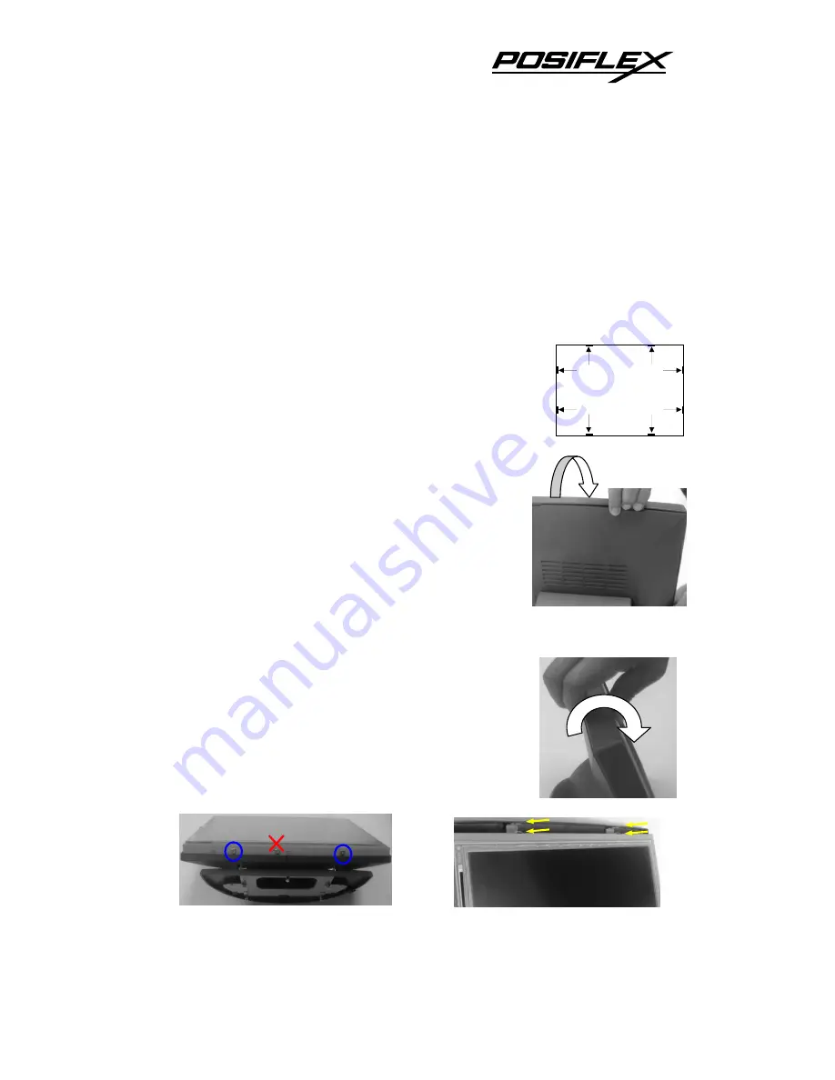
Please first notice the 8 hooks on the front bezel holding the
back cover at about 6 cm (2.5”) away from each corner. The
simplified drawing on the left indicates the positions of
these hooks as viewed from the back of the display screen.
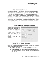
It takes some skill and strength to get the front bezel
unhooked from the back cover. The pictures at right
indicate the position and force to engage for this operation.
Please keep cautious not to get scratch/damage on the touch
panel or LCD panel.
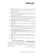
Remove the 2 blue-circled flat head screws on bottom edge
of the LCD and touch panel assembly in lower left picture.
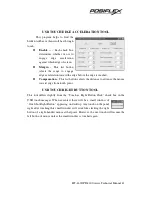
Lift this bottom edge and gently unhook the panel assembly
from metal bracket in back cover at top edge at the yellow
arrows in the lower right picture.
Hooks from
Front Bezel
h
g
f
e
d
c
b
a

