26
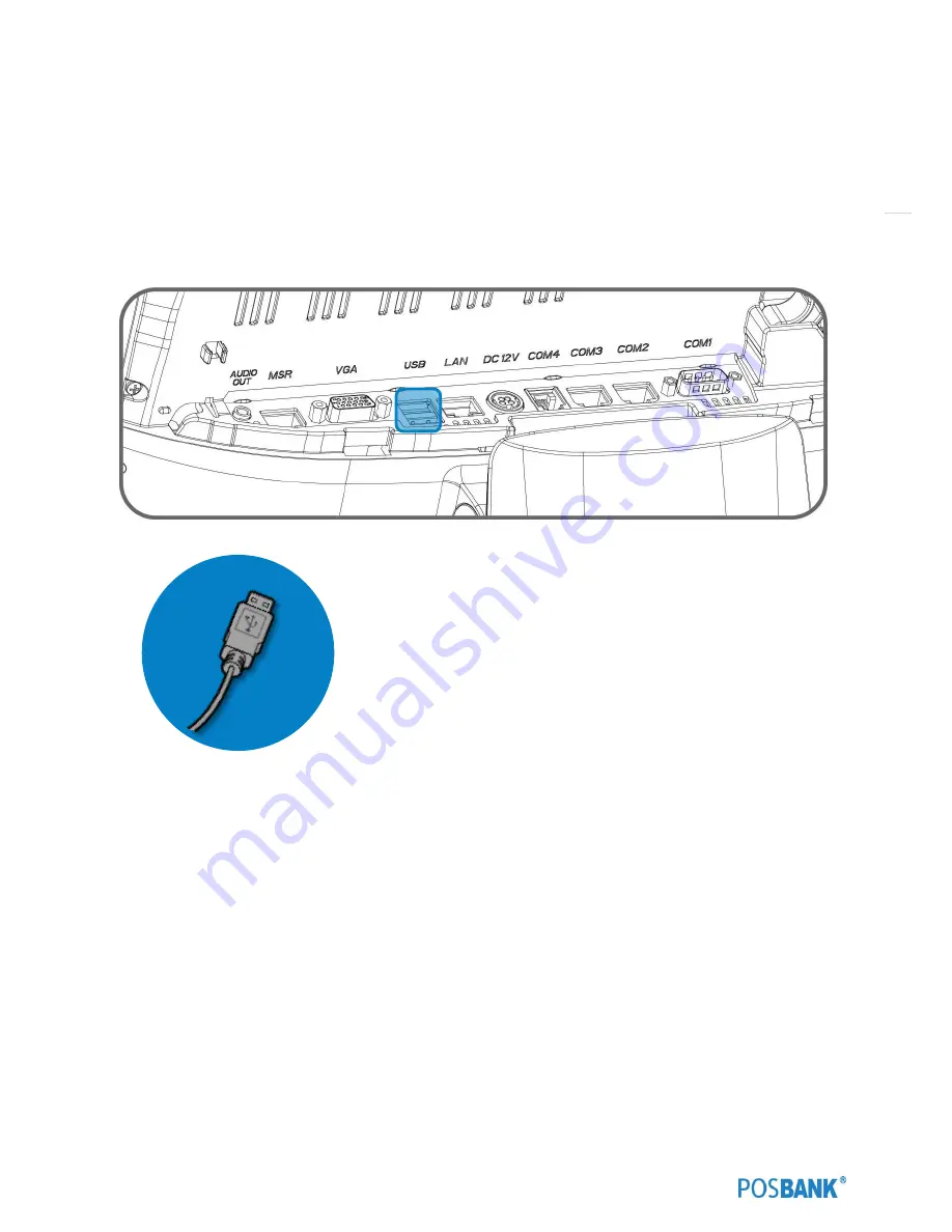
(7) Setting up: Connection USB Port
USB ports are provided in the POS unit, two at the rear I/O and four at the side, all of which support the standard USB
2.0.
Some USB devices (optional devices) are only functional with specific driver software installed.
If multiple USB devices are used together, this may result in abnormal functionality.
Using a USB hub with external adapter for supplying power is recommended.
Dependent on the type of device, it is possible for the USB device to be recognized later than normal.
Содержание APEXA G
Страница 1: ...USER manual APEXA_G PBUM E Rev001 160509 Point of sale system APEXA G...
Страница 7: ...7 1 Specification Outline size...
Страница 8: ...8 3 Specification ExplodeView...
Страница 18: ...18 Optional Devices CDP Optional Devices 2nd Display 9 7 inch...
Страница 19: ...19 Optional Devices 2nd Display 12 1 inch Optional Devices 2nd Display 15 inch...
Страница 21: ...21 4 Configuration Refer to following diagram to identify the components on this side of the system Front view...
Страница 22: ...22 Back view...
Страница 24: ...24 Standard I O port...
Страница 29: ...29 10 Setting up Printer Connection Connect printer cable to either Serial USB port as required...
Страница 37: ...37 Mother board Step4 Separated six screws of rear case Step5 Push the rear case to refer the image...
Страница 39: ...39 Mother board Step8 Separated the touch cable and another cables Step9 Replace the mother board...
Страница 41: ...41 Power PCB Step4 Separated six screws of rear case Step5 Push the rear case to refer the image...
Страница 42: ...42 Power PCB Step6 Separated two screws and replace power PCB ZOOM IN...
Страница 44: ...44 MSR module Step4 Put MSR module in the MSR bracket Step5 Connect the cable to MSR port...
Страница 46: ...46 MSR module Separate it while pushing the hook which is located in the bottom of MSR...
Страница 50: ...50 2nd display module...
Страница 57: ...57 Wall mount Step7 Fix vesa bracket A B with the screws D...
Страница 59: ...59 Arrangement of the cable Step4 Assemble the I O cover Step5 Assemble upper and push the bottom...
Страница 72: ...72 2 6 IDE Configuration...
Страница 74: ...74...
Страница 77: ...77 2 9 Hardware Monitor Smart Fan Mode configuration Smart Fan Mode select...
Страница 78: ...78 2 10 Chipset...
Страница 79: ...79 2 11 South Bridge South bridge parameters...
Страница 80: ...80 2 12 North Bridge...
Страница 81: ...81 2 13 Boot Display Configuration...
Страница 82: ...82 2 14 Boot...
Страница 83: ...83 2 15 Security Administrator password Set administrator password User password Set User password...
Страница 84: ...84 2 16 Azalia HD Audio...
Страница 85: ...85 2 17 Info Report Configuration...
Страница 86: ...86 2 18 Intel IGD Configuration...
Страница 87: ...87 2 19 O E M Settings...
Страница 88: ...88 2 20 PPM Configuration...
Страница 89: ...89 2 21 Realtek PCIe GBE Family Controller...
Страница 90: ...90 2 22 Socket 0 CPU Information...


