background image

7-ENG

DESCRIPTION OF OPERATION

Drain Valve (not shown):

 The drain valve is located at the base of the air  tank and

is used to drain condensation at the end of each use.

Motor Thermal Overload Protector (not shown):

  The electric motor has an

automatic thermal overload protector. If the motor overheats for any reason, the
thermal overload protector will shut off the motor. The motor must be allowed to
cool before restarting.

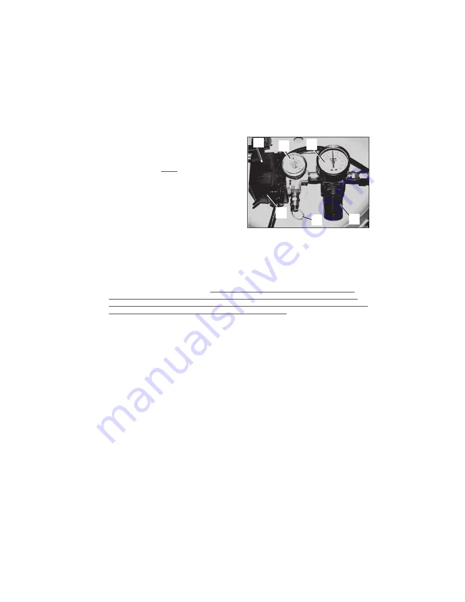
ON/AUTO - OFF Switch (A) Fig. 1:

 Turn this switch ON to provide automatic

power to the pressure switch and OFF to remove power at the end of each use.

Air Intake Filter (not shown):

  This filter is designed to clean air coming


into the

pump. This filter 

must

 always be clean and ventilation openings free from

obstructions. See "Maintenance".

Air Compressor Pump (not shown): 

 To compress air, the piston moves up and

down in the cylinder.  On the downstroke, air is drawn in through the air intake
valves. The exhaust valve remains closed.  On the upstroke of the piston, air is
compressed.  The intake valves close and compressed air is forced out through the
exhaust valve, into the outlet tube, through the check valve and into the air tank.
Working air is not available until the compressor has raised the air tank pressure
above that required at the air outlet.

Check Valve (not shown): 

 When the air compressor is operating, the check valve

is “open”, allowing compressed air to enter the air tank.  When the air compressor
reaches “cut-out” pressure, the check valve “closes”, allowing air pressure to
remain inside the air tank.

Pressure Release Valve (not shown): 

 The pressure release valve located on the

side of the pressure switch, is designed to automatically release compressed air
from the compressor head and the outlet tube when the air compressor reaches
“cut-out” pressure or is shut off. The pressure release valve allows the motor to
restart freely. When the motor stops running, air will be heard escaping from this
valve for a few seconds.  No air should be heard leaking when the motor is running,
or continuous leaking after unit reaches cut-out pressure.

Pressure Switch (B) Fig. 1: 

The pressure switch automatically starts the motor

when the air tank pressure drops below the factory set “cut-in” pressure. It stops
the motor when the air tank pressure reaches the factory set “cut-out” pressure.

Safety Valve (C) Fig. 1: 

If the pressure switch does not shut off the air compressor

at its cut-out pressure setting, the safety valve will protect against high pressure by
“popping out” at its factory set pressure (slightly higher than the pressure switch
cut-out setting).

Outlet Pressure Gauge (D) Fig. 1: 

 The outlet pressure gauge indicates the air

pressure available at the outlet side of the regulator. This pressure is controlled by
the regulator and is always less than or equal to the tank pressure.

Tank Pressure Gauge (E) Fig. 1: 

 The tank pressure gauge indicates the reserve air

pressure in the tank.

Regulator (F) Fig. 1:

 The air pressure coming from the air tank is controlled by the

regulator knob. Turn the knob clockwise to increase pressure and counterclockwise
to decrease pressure. To avoid minor readjustment after making a change in
pressure setting, always approach the desired pressure from a lower pressure.
When reducing from a higher to a lower setting, first reduce to some pressure less
than that desired, then bring up to the desired pressure. Depending on the air
requirements of each particular accessory, the outlet regulated air pressure may
have to be adjusted while you are operating the accessory.

Fig. 1

B

A

E

D

F

C

Содержание CPF23400P

Страница 1: ...n the frame Record these numbers in the spaces below and retain for future reference Model No Type Serial No ESPA OL P GINA 19 FRAN AISE PAGE 37 IMPORTANT Please make certain that the person who is to...

Страница 2: ...e nearest Autho rized Service Center for ordering repair parts and for warranty repairs When ordering repair parts from your local Authorized Service Center always give the following information Model...

Страница 3: ...IRE AIR TANK THE FOLLOWING CONDITIONS COULD LEAD TO A WEAKENING OF THE TANK AND RESULT IN A VIOLENT TANK EXPLOSION AND COULD CAUSE PROPERTY DAMAGE OR SERIOUS INJURY HAZARD WHAT CAN HAPPEN HOW TO PREVE...

Страница 4: ...AIR FROM THE COMPRESSOR EITHER DIRECTLY OR FROM A BREATHING DEVICE CONNECTED TO THE COMPRESSOR WORK IN AN AREA WITH GOOD CROSS VENTILATION READ AND FOLLOW THE SAFETY INSTRUCTIONS PROVIDED ON THE LABEL...

Страница 5: ...AFTER OPERATION COMPRESSOR WILL REMAIN HOT FOR SEVERAL MINUTES AFTER OPERATION DO NOT REACH AROUND PROTECTIVE SHROUDS OR ATTEMPT MAINTENANCE UNTIL UNIT HAS BEEN ALLOWED TO COOL A PORTABLE COMPRESSOR C...

Страница 6: ...es Standards for Safety Porter Cable air compressors should be operated on not more than a 50 duty cycle This means an air compressor that pumps air more than 50 of one hour is considered misuse becau...

Страница 7: ...compressed air from the compressor head and the outlet tube when the air compressor reaches cut out pressure or is shut off The pressure release valve allows the motor to restart freely When the motor...

Страница 8: ...must be used use only a 3 wire extension cord that has a 3 blade grounding plug and a 3 slot receptacle that will accept the plug on the extension cord make sure the extension cord is in good conditio...

Страница 9: ...the same configuration as the plug See Fig 3 DO NOT USE AN ADAPTER Inspect the plug and cord before each use Do not use if there are signs of damage Improper grounding can result in electrical shock D...

Страница 10: ...rain water from air tank by opening drain cock valve on bottom of tank WATER WILL CONDENSE IN THE AIR TANK IF NOT DRAINED WATER WILL CORRODE AND WEAKEN THE AIR TANK CAUSING A RISK OF AIR TANK RUPTURE...

Страница 11: ...ll air tank pressure and allow unit to cool before doing any maintenance or repair Never operate the unit with the belt guard removed To ensure efficient operation and longer life of the air compresso...

Страница 12: ...otor Wiring Diagram The motor connection diagram is located on the side of motor STORAGE Before you store the air compressor make sure you do the following 1 Review the Maintenance section on the prec...

Страница 13: ...NOT OVER TIGHTEN Air leaks at or inside check valve Malfunctioning or dirty check valve A malfunctioning check valve results in a constant air leak at the pressure release valve when pressure is in th...

Страница 14: ...cessary Have checked by an Authorized Warranty Service Center Do not operate the compressor in the paint spray area See flammable vapor warning 1 Check fuse box for blown fuse and replace if necessary...

Страница 15: ...e in hose Check valve restricted Air leaks Decrease amount of air usage Check the accessory air requirement If it is higher than the SCFM or pressure supplied by your air compressor you need a larger...

Страница 16: ...tion of components within the air line Do not mix different styles of bodies plugs HOSE 3 8 I D HOSE Ideal for increasing working distance in high CFM applications 1 4 COIL HOSE Self retracting and li...

Страница 17: ...17 ENG NOTES...

Страница 18: ...erials or other contaminants Expendable items that become worn during normal use such as drain valves fuses filters belts air cleaners spark plugs engine oil and pump oil Cosmetic defects that do not...

Отзывы: