32
33
Pre-installation requirements
Planning
Planning the Overlay™ system beforehand will save time during
installation and minimise product waste.
The direction the pipe runs to and from the ZRU or manifold and
use of the return bends will be the main considerations.
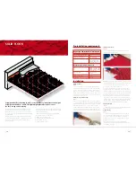
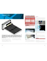
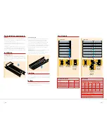
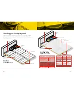
The end returns have a flat panel which forms a channel to allow
the routing of pipes to multiple circuits in the room. This can be
removed where necessary.
Floor areas which don’t require pipe circuitry, e.g. beneath kitchen
cupboards or sanitary ware, can be ‘blanked’ using 18mm plywood
or chipboard. This will make better use of the Overlay™ products.
This can also be used to ‘square off’ rooms with irregular walls.
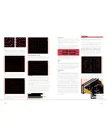
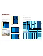
Example of ‘blanking’ on kitchen plan
Example of ‘blanking’ in a bathroom
Example of ‘squaring off’ an irregular room plan
Room layouts
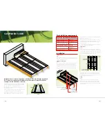
The following diagrams show some examples of room shapes,
pipe requirements and interruptions (pillars, hearths, etc.)
which need to be accommodated.
Room with 2 circuits
Room with pillars/hearth
Pipe layouts in multiple room installations
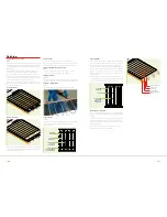
Multiple room installations require several circuits and careful
planning is required close to the manifold to allow for all pipes
to be accommodated.
Wherever possible pipes can simply go through, rather than
round, walls to eliminate the number of pipes requiring access
through the entrance of the manifold cupboard.
Alternatively leave voids at the edge of the panels.
Using return bends as routers or using supply pipes
to heat corridors are all ways of managing the installation
in this area.
2
4
3
2
3
4
1
1
End Return
with panel
removed
End Return
End Return
with panel
removed
End Return

