background image

RealPresence Collaboration Server (RMX) 2000 Hardware Guide 

1-18

Polycom, Inc.

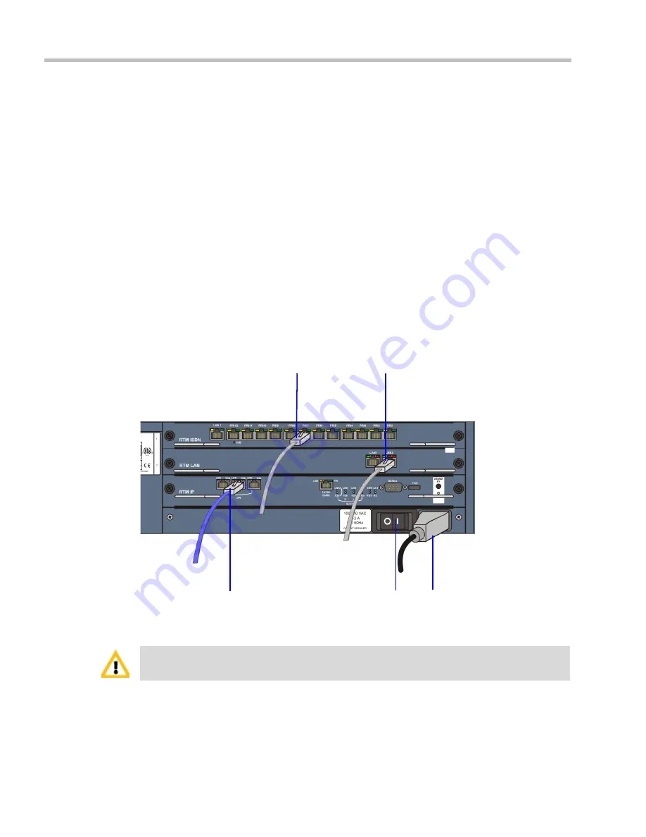
Cables Connected to the RTM IP, RTM LAN and RTM ISDN Cards

All external connectors are located on the rear panel.

To connect the cables:

Required. RTM-IP 2000

:

Connect the LAN cable to 

LAN 2.

Optional.

 Connect the additional LAN cable to 

LAN 1. 

This port is also available 

for Media Redundancy.


For more information, see 

Polycom® RealPresence® 

Collaboration Server 1500, 2000, 4000 , 

"

LAN Redundancy” 

on page

16-37

 and 

"Multiple Network Services” 

on page

16-53

.

Optional. 

For each installed 

RTM LAN

 - Connect the LAN cable to 

LAN 2.

Optional. 

Connect the LAN cable to 

LAN 1. 

With Multiple networks and LAN 

redundancy configurations, ports LAN 1 and LAN 2 can be used. For more 
information, see 

Polycom® RealPresence® Collaboration Server 1500, 2000, 4000 , 

"

LAN Redundancy” 

on page

16-37

 and 

"Multiple Network Services” 

on page

16-53

.

Optional. 

For each installed 

RTM ISDN

:

Connect the E1/T1 cables to their 

PRI

 Ports.

Connect the LAN cable to 

LAN 1.

Figure 1-10

 RMX 2000 Rear Panel View with Cables

LAN 2 Connection

Power 

Cable

Off/On 

switch

E1/T1 Connection

LAN 2 Connection, (optional) LAN

Do not remove the protective caps from LAN1*, LAN 3 and ShMG ports on the RTM IP card. 

Содержание Collaboration Server (RMX) 2000

Страница 1: ... Type the document title Polycom Document Title 1 Version 8 1 June 2013 DOC2728A Polycom RealPresence Collaboration Server RMX 2000 Hardware Guide ...

Страница 2: ...sion is available on the Polycom Support page for the Polycom RealPresence Collaboration Server RMX 2000 system This software has not achieved UC APL certification 2013 Polycom Inc All rights reserved Polycom Inc 6001 America Center Drive San Jose CA 95002 USA No part of this document may be reproduced or transmitted in any form or by any means electronic or mechanical for any purpose without the ...

Страница 3: ...not based on mercury lead or cadmium technologies Batteries in this product are not intended to be replaced or removed by the user Additional information on the safe use and recycling of batteries can be found at www polycom com batteries United States Federal Communication Commission FCC This equipment has been tested and found to comply with the limits for a Class A digital device pursuant to Pa...

Страница 4: ... Direktīvas 1999 5 EK būtiskajām prasībām un citiem ar to saistītajiem noteikumiem Lietuvių Lithuanian Šiuo Polycom UK Ltd deklaruoja kad šis Polycom RMX atitinka esminius reikalavimus ir kitas 1999 5 EB Direktyvos nuostatas Nederlands Dutch Hierbij verklaart Polycom UK Ltd dat het toestel Polycom RMX in overeenstemming is met de essentiële eisen en de andere relevante bepalingen van richtlijn 199...

Страница 5: ...quipment USOC Jacks RJ48S Service Order Code 6 0N Facility Interface Code 04DU9 DN 04DU9 BN 04DU9 1KN 04DU9 1SN If this equipment causes harm to the telephone network the telephone company will notify you in advance that temporary discontinuance of service may be required But if advance notice isn t practical the telephone company will notify the customer as soon as possible Also you will be advis...

Страница 6: ......

Страница 7: ...ecting Cables to the RealPresence Collaboration Server RMX 2000 1 12 RealPresence Collaboration Server RMX 2000 Components 1 13 RealPresence Collaboration Server RMX 2000 Front Panel 1 13 RealPresence Collaboration Server RMX 2000 Rear Panel 1 15 RTM IP 1 15 RTM ISDN 1 16 ISDN PSTN Clock Source 1 17 RTM LAN 1 17 Cables Connected to the RTM IP RTM LAN and RTM ISDN Cards 1 18 MPM MPM and MPMx Media ...

Страница 8: ...PM MPM MPMx Card 1 34 Installing a New MPM MPM MPMx Card in a Powered On RealPresence Collaboration Server RMX 2000 1 34 Replacing the RTM IP Card 1 34 Removing the Blank Cover from the Rear Panel 1 35 Installing or Replacing the RTM ISDN Card 1 36 Removing the Blank Cover 1 36 Removing an Existing Card RTM ISDN Card 1 36 Installing a New or Replacement RTM ISDN Card 1 36 Installing or Replacing t...

Страница 9: ...d Chassis based on the ATCA standard Support for standard network interfaces IP ISDN and LAN and large number of ports H 323 SIP PSTN and ISDN New hardware technologies Telco grade high availability redundancy on line upgrading and dynamic resource allocation Easy integration of conference elements into external network management Enhanced Continuous Presence multi image video IVR Interactive Voic...

Страница 10: ...o and Siren LPR Video H 261 H 263 H 264 H 264 High Profile Network Interfaces IP ISDN PSTN and LAN H 323 SIP ISDN PSTN VoIP and LAN Power Supply AC Input Range BTU Voltage range 100 240 VAC 10 4 8 AMP 50 60 Hz Maximum BTU output 2390 per hour Power Consumption AC Maximum Power consumption 900 Watts Environment Operating temperature 0 to 40 C 32 to 104 F Storage temperature 40 to 70 C 40 to 158 F R...

Страница 11: ...es 200 400 400 Maximum number of Meeting Rooms 1000 1000 1000 Maximum number of Entry Queues 40 40 40 Maximum number of Profiles 40 40 40 Maximum number of Conference Templates 100 100 100 Maximum number of SIP Factories 40 40 40 Maximum number of IP Services 2 2 2 Maximum number of ISDN Services 2 2 2 Maximum number of IVR Services 40 40 40 Maximum number of Recording Links 20 default 20 default ...

Страница 12: ...ties RMX 2000 System Functions MPM Mode MPM Mode MPMx Mode System Resources are now reported in terms of HD720p30 CP ports One HD video port equals 3 CIF video ports Table 1 3 System Resource Capacities per Resolution per Card Type in CP Resource Type and Resolution Resources with MPM Resources with MPM Resources with MPMx PSTN 400 400 400 VOIP 400 800 720 CIF H 263 80 160 120 CIF H 264 80 160 180...

Страница 13: ... outlet that has a protective ground contact Ensure that the power cord is easily accessible from the back of the system at all times Place the equipment in a well ventilated area where the vents are free from obstruction Do not place heavy objects directly on top of the RMX 2000 unit Do not use liquids around your equipment Rack Mount Safety Precautions The following precautions should be followe...

Страница 14: ...ur MCU operating in case of a power failure Place the RMX 2000 on a hard flat surface such as a desktop or mount it on 19 rack The airflow of the RMX 2000 is from right to left Be sure that the areas in the left and right side of the system are clear for proper ventilation Installing the RealPresence Collaboration Server RMX 2000 The following procedures have to be performed to install the RMX 200...

Страница 15: ...document you received with your shipment For more information on installing the ISDN card see Installing or Replacing the RTM ISDN Card on page 1 36 Telescopic Rail Runner Assembly for RealPresence Collaboration Server RMX 2000 Before installing the telescopic rail runners in the rack make sure that the kit has the following parts Write down the RMX s serial number that is on a sticker on the back...

Страница 16: ... spacer assembly kit Rack spacer 3 Front Rear 4 Flat head screw M5 10mm 4 8 Rail runner assembly kit Flat head screw M3 8mm 5 4 Flat washer M3 6 4 Nut spring M3 7 4 RMX chassis assembly kit Pan head screw M5 12mm 8 2 Flat washer M5 9 2 Table 1 5 Rail Runners Kit Contents Part Kit no Item Item no Item Sample Item Quantity Rack Rail Runners require a minimum of 48cm and a maximum of 80cm within the ...

Страница 17: ...ng that the system can be horizontally seated Figure 1 1 Front view of RMX Rail Runner Assembly 2 Position the Rack Spacer item no 3 onto the marked rack post together with left rack rail runner item no 1 which is labeled LEFT and fasten the flat head screws 3 10mm item no 4 as shown in the following figure Figure 1 2 Detail of Front Rack Spacer Assembly left rail runner is shown here for all RMX ...

Страница 18: ...lat washer item 6 and nut spring item 7 in the middle of the telescopic rack rail runner for added stability as shown in Figure 1 4 Figure 1 4 Detail of Left Rail Runner front internal view 6 Repeat step 5 for the right rack rail runner On the RMX1500 4000 the center hole on the Rack Spacer must be left clear as it is required for fixing the RMX to the rack post See Figure 1 2 On the RMX 2000 the ...

Страница 19: ...rackets supplied by the rack manufacturer in the rack Mount the RMX 2000 on top of the rack brackets Fasten the RMX to the rack with screws through the four holes in the RMX s front mounting brackets Using a shelf Install the shelf supplied by the rack manufacturer in the rack Mount the RMX on the shelf Fasten the RMX to the rack with screws through the four holes in the RMX s front mounting brack...

Страница 20: ...er 1500 2000 4000 Administrator s Guide LAN Redundancy on page 16 37 and Multiple Network Services on page 16 53 Connect the LAN cable to LAN 1 Optional If an RTM ISDN card is installed on the RMX 2000 connect the E1 T1 Cables to PRI Ports Do not remove the protective caps from LAN1 LAN3 and ShMG ports LAN 2 Connection Power Cable Off On switch E1 T1 Connection LAN 2 Connection optional LAN1 An RM...

Страница 21: ...se For more information contact your next level of support Table 1 6 RMX 2000 Component Description Component Description CNTL CPU Module The CNTL module controls and manages the RMX 2000 The CNTL module has an ComExpress Pentium M 1 4GHz processor a 40GB hard disk drive 1GB Compact Flash and 1GB of DDR RAM The Operating System is Linux Power Supply Drawer The Power Supply drawer is located below ...

Страница 22: ...urces Notes The MPM card s can only work with software version 4 0 or later Ensure that software appropriate to the MCU hardware configuration is installed in the MCU The MPM card can work only with a new environmentally friendly D type chassis and is disabled when inserted in a C type chassis Multi Processor Modulex MPMx Card The MPMx cards perform the various RTP audio and video processing funct...

Страница 23: ...ections include 3 LAN ports 10 100Mb ShMG port Future Use 1 Serial port Future Use 1 USB port Figure 1 7 RMX 2000 RTM IP Rear Panel Layout The following items appear on the RMX 2000 rear panel LAN1 LAN3 and the 10 100Mb ShMG ports shall not be used and the plastic caps covering those ports should not be removed With Multiple networks and LAN redundancy configurations LAN 1 port is used For more in...

Страница 24: ... and RTM ISDN cards Each RTM ISDN card includes the following connections Figure 1 8 RMX 2000 RTM ISDN Rear Panel Layout LAN 3 For Remote Access only using the Alternate Management Network For more information see the RealPresence Collaboration Server RMX 1500 2000 4000 Administrators Guide Administrator s Guide Appendix G Configuring the Workstation on page F 1 Note When not in use LAN 3 is cover...

Страница 25: ...N card must connect directly to an MPM MPMx card In an RealPresence Collaboration Server RMX 1500 2000 4000 Administrators Guide with a single MPM MPMx card the RTM LAN card must be installed in the rear panel slot on the same level as the MPM MPMx card Each RTM LAN card includes 2 LAN ports and a maximum of two RTM LAN cards can be installed on the RMX 2000 The LAN 1 and LAN 2 ports on the RTM LA...

Страница 26: ... on page 16 53 Optional For each installed RTM LAN Connect the LAN cable to LAN 2 Optional Connect the LAN cable to LAN 1 With Multiple networks and LAN redundancy configurations ports LAN 1 and LAN 2 can be used For more information see Polycom RealPresence Collaboration Server 1500 2000 4000 LAN Redundancy on page 16 37 and Multiple Network Services on page 16 53 Optional For each installed RTM ...

Страница 27: ...e for all card types Table 1 8 summarizes the resource capacities of the various resolutions per card type in CP Conferencing Mode Table 1 9 summarizes the resource capacities per line rate per card type in VSW Conferencing Mode Table 1 8 MPMx MPM and MPM Resource Capacity per Resolution in CP Resource Type Maximum Possible Resources Per Card MPM MPM MPMx HD720p60 HD1080p30 Symmetric Not Applicabl...

Страница 28: ...f the various MPM card assemblies MPMx Resource Capacities per Card Assembly The MPMx card offers increased resource capacities and capabilities Two MPM card assemblies are available MPMx D MPMx S Table 1 11 summarizes the video capacities of the two MPMx card assemblies Table 1 10 MPM Card Assemblies and Capacities for CP Conferences Card Type Resources Bandwidth Voice CIF SD 30fps HD720p 30fps H...

Страница 29: ...nfiguration Mode Table 1 12 summarizes the Operating Mode After Next Restart resulting from of adding or swapping MPM MPM MPMx cards in a running system The RMX switches between MPM MPM and MPMx Card Configuration Modes when MPM MPM MPMx cards are removed or swapped while the system is running The switch between Card Configuration Modes occurs during the next restart Installing or swapping MPM MPM...

Страница 30: ...ng MPM card is disabled Example 2 Current status An RMX has one MPMx card installed The Card Configuration Mode is MPMx and the MPMx card is enabled Action 1 Remove the MPMx card 2 Insert one MPM card Result The Card Configuration Mode remains MPMx The inserted MPM card is disabled After Reset The Card Configuration Mode is MPM The inserted MPMx card is disabled The remaining MPM card is enabled M...

Страница 31: ...onfiguration Mode is MPM and the MPM card is enabled Action Insert one MPMx card Result The Card Configuration Mode remains MPM MPM card is enabled The inserted MPMx card is disabled After Reset The Card Configuration Mode is MPMx The inserted MPMx card is enabled The remaining MPM card if not removed is disabled ...

Страница 32: ...he power cable is unplugged the FAIL LED is lit 2 3 seconds before turning OFF MPM MPM MPMx Card ERR Red ON Major error on card Flashes During card startup RDY Green ON The card has completed startup successfully after the ERR RDY ACT LED s have stopped flashing Flashes During card startup ACT Amber ON At least one participant is connected to a conference Flashes During card startup HS Blue Flashe...

Страница 33: ...one endpoint is connected to the system Flashes During system startup HD Red OFF Normal Flashes Hard disk is active HS Blue Flashes Indicates when the power down process is initiated on an MPM MPM MPMx card This LED flashes in synchronization with the MPM MPM MPMx s cards HS LED OFF Normal ON CPU may be removed Table 1 13 RMX 2000 Front Panel LED s Continued Component LED ID LED Color Description ...

Страница 34: ... during initial power up STANDBY LED Green When the user in the RMX Manager RealPresence Collaboration Server Client presses the System Shut Down red button in the Hardware Monitor tool bar the system should enter a standby mode and the LED turns ON Only the media and control unit cards are in a standby mode Shelf Manager remains active Turn the system OFF ON to exit the standby mode Table 1 15 RM...

Страница 35: ...Name LED Color Description LAN 1 2 LEDs 1 Gb Amber ON when 1Gb connection is online flickers with Packet activity LNK Green ON with an active network connection flickers with Packet activity HS LED Blue OFF Normal Flashes During the startup of a media card and control unit Also flashes when the RTM LAN card is powered down ON RTM LAN card may be removed ...

Страница 36: ...e with MPM MPMx card s The chassis type can be viewed in the Hardware Monitor by right clicking Slot 0 and then clicking Properties The RMX 2000 General Information dialog box opens The RMX Part Number contains the letter A B C D that represents the chassis type as shown in the capture above For more details see the RealPresence Collaboration Server RMX 1500 2000 4000 Administrators Guide Chapter ...

Страница 37: ...jector levers can be attached to the cards An all metal silver lever A modified PMC compatible ejector lever covered by plastic caps with a lock catch Using the All Metal Ejector Lever This ejector lever can be moved to 3 positions Closed The ejector levers are fully retracted and pushed up against the card s panel Partially Open For card powering down mode Partially open the ejector lever s until...

Страница 38: ...dule 1 Ensure that power switch on the RMX 2000 is turned OFF O 2 Unscrew the captive screws on the front panel of the RMX 2000 that secure the CNTL Module 3 Use the metal ejector lever to pull the CNTL Module out of its slot in the Backplane Handle Unlocking the Lock Catch With your thumb holding the handle and your index finger shifting the catch to left gently pull the handle away from the chas...

Страница 39: ...e Power Supply Module A single supply unit powers the RMX 2000 Use the following procedure to replace a Power Supply 1 Ensure that the power switch on the RMX 2000 is turned OFF O and that the power cords are disconnected from the MCU 2 Unscrew the captive screws on the front panel of the RMX 2000 that secure the Power Supply unit 3 Use the finger grip to pull the Power Supply unit out of its slot...

Страница 40: ...tive screws on the front panel of the RMX 2000 that secure the Fan drawer 2 Use the metal ejector levers to pull the Fan drawer out of its slot in the Backplane 3 Carefully slide the Fan drawer out through the front panel 4 Slide in the replacement Fan drawer 5 Push the Fan drawer firmly into the Backplane making sure it is properly seated in its slot 6 Tighten the captive screws on the front pane...

Страница 41: ...or each disconnected participant a participant disconnection event is written to the CDR with the disconnection cause Disconnected by Operator New participant connections are blocked when the card is removed If an RTM ISDN card is connected to the MPM MPM MPMx card it is also powered off and all ISDN and PSTN participants are disconnected When an RTM ISDN card is removed its resources are deducted...

Страница 42: ...ctor levers to their full open position 3 Insert the card into the slot until the ejector levers touch the front edge of the card cage 4 Push the ejector levers to their closed position and tighten the captive screws on each side of the card securing the MPM MPM MPMx card to the RMX The blue HS LEDs on the MPM MPM MPMx card and the Control Unit start flashing and the power on cycle for the card is...

Страница 43: ...ts 8 Ensure that the metal ejector levers are fully retracted into their housings 9 Tighten the captive screws on the rear panel of the RMX 2000 that secure the RTM IP card 10 Turn ON the RMX 2000 Removing the Blank Cover from the Rear Panel Use the following procedure to remove the blank cover 1 Ensure that the power switch circuit switch on the RMX is turned OFF O 2 Unscrew the captive screws on...

Страница 44: ...n page 1 35 Removing an Existing Card RTM ISDN Card 1 Ensure that the power switch on the RMX 2000 is turned OFF O 2 Unscrew the captive screws that fasten the card to the MCU Use the metal ejector levers to pull the card out of its slot from the backplane 3 Slide out the RTM ISDN card Installing a New or Replacement RTM ISDN Card 1 On the new RTM ISDN card move the ejector levers to their fully o...

Страница 45: ...tion see RealPresence Collaboration Server RMX 1500 2000 4000 Administrators Guide Chapter 16 Adding Modifying ISDN PSTN Network Services on page 16 45 Installing or Replacing the RTM LAN The RTM LAN card on the rear of the RMX 2000 provides connectivity to all the MCU modules The RTM LAN card must be seated opposite to an MPM MPMx card located in the top slots on the front of the RMX Removing the...

Страница 46: ...e the ejector levers to their fully open position 2 Slide in the replacement RTM LAN card 3 Push the RTM LAN card firmly into the backplane making sure it is properly seated in its slots 4 Ensure that the metal ejector levers are fully retracted into their housings 5 Tighten the captive screws on the rear panel of the RMX 2000 that secure the RTM LAN card 6 Reconnect the cables 7 Turn ON the RMX 2...

Страница 47: ...dix A Pin Assignment PRI Port Assignment Table A 1 PRI Port Assignment Pin Signal Name 1 Receive Ring 2 Receive Tip 3 No connection 4 Transmit Ring 5 Transmit Tip 6 No connection 7 No connection 8 No connection Pin 8 Pin 1 ...

Страница 48: ...Polycom RealPresence Collaboration Server RMX 2000 Hardware Guide A 2 Polycom Inc ...

Отзывы: