
4
SAFETY INSTRUCTIONS
Tool Opera
ti
on
The employer is responsible for ensuring that the manufacturer’s
tool opera
ti
ng/safety instruc
ti
ons are available to operators.
The employer and the tool operator are responsible for the safe use
of the tool.
The employer and tool operator are responsible for selec
ti
ng an
appropriate tool actua
ti
on system from op
ti
ons available, taking into
considera
ti
on the work applica
ti
ons for which the tool is used.
It is the responsibility of the employer and the tool operator to
ensure that the tools are used only when the tool operator and
all other personnel in the work area are wearing eye protec
ti
on
equipment and when required, other appropriate protec
ti
on
equipment such as head, hearing and foot protec
ti
on equipment.
Safety Eye and Face Protec
ti
on Equipment
Safety eye and face protec
ti
on equipment shall conform to the
requirements of ANSI Z87.1 and shall provide protec
ti
on against
fl
ying par
ti
cles both from the front and side or shall be determined
by the U.S.
D
epartment of Labor’s Occupa
ti
onal Safety and Health
Administra
ti
on (OSHA) to provide protec
ti
on equivalent to eye
protec
ti
on conforming to the requirements of ANSI Z87.1 and shall
provide protec
ti
on against
fl
ying par
ti
cles both from the front and
side.
Head Protec
ti
on Equipment
Head protec
ti
on shall conform to American Na
ti
onal Standards
Ins
ti
tute Z89.1, “Protec
ti
ve Headwear for Industrial Workers”.
T
OOL
M
AINTENANCE
When working on air tools note the warnings in this manual and use
extra care when evalua
ti
ng problem tools.
Responsibility for Proper Tool Maintenance
The employer and tool operator are responsible for assuring that the
tool is kept in safe working order as described in the Tool Opera
ti
ng/
Safety Instruc
ti
ons.
Only quali
fi
ed personnel shall repair the tool.
The employer is responsible for ensuring that the manufacturer’s
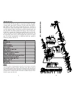
17
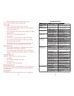
475
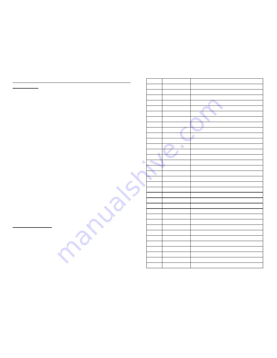
Part Number
Descrip
ti
on
33
47533
PIN, TRI
GG
ER (10033)
34
47534
PIN (10034)
35
47535
ROLLER (10035)
36
47536
O-RIN
G
(10036)
37
47537
SCREW, SHCS (10037)
38
47538
PIN (10038)
39
47539
ROLLER (10039)
40
47540
PIN (10040)
41
47541
O-RIN
G
(10041)
42
47542
TRI
GG
ER VALVE PLUN
G
ER (10042)
43
47543
SPRIN
G
, TRI
GG
ER VALVE (10043)
44
47544
TRI
GG
ER VALVE STEM (10044)
45
47545
O-RIN
G
(10045)
46
47546
O-RIN
G
(10046)
47
47547
TRI
GG
ER VALVE HOUSIN
G
(10047)
47U
47586
TRI
GG
ER VALVE UNIT (10047U)
48
47548
HOL
D
PLATE (10048)
49
47549
SCREW (10049)
50
47550
SPRIN
G
(10050)
51
47551
ARM
G
UI
D
E (10051)
52
47552
SPRIN
G
(10052)
53
47553
SAFETY ARM B (10053)
54
47554
SCREW, HHCS (10054)
55
47555
FRONT
G
UI
D
E (10055)
56
47556
ARM COVER (10056)
57
47557
SAFETY ARM A (10057)
58
47558
INSERT, NOSE (10058)
59
47559
NOSE (10059)
60
47560
PLATE,
D
RIVER (10060)
61
47561
FOOT (10061)
62
47562
KNOB (10062)
63
47563
MA
G
AZINE, FIXE
D
(10063)
64
47564
STOP PLATE (10064)
65
47565
SCREW, SHCS (10065)