11
User manual
En
gli
sh
13.5 LED indicators
D1: LED on - the gate is not completely closed
Led off - the gate is completely closed
D2: LED on - the gate is not fully open
Led off - the gate is fully open
D3: LED on - if you give, for example, the opening command from two
connected access terminals, the LED will flash to warn that the same
command has been given.
D4: Led on - infrared sensors have not detected any obstacles
LED off - infrared sensors have detected an obstacle. The engine will stop.
D6: Led on - gate opening
D7: Led on - door closed
D8: LED on - the Mainboard is powered
13.6 Terminal stop detection interface:
It has 2 modes: one opens the gate and one closes the gate in normal operation.
13.7 Open / close limit setting (J1):
Jumper J1 communicates to the terminal 13.6 the direction of opening and
closing the gate. Jumper J1 variants:
1. NO1-NO2 - Normal opening (Motor on the left of the gate inside);
2. NO2-NO3 - Opening in the opposite direction. (Motor to the right of
the gate inside) It requires changing the direction of the motor supply (see
installation and motor connection chapter).
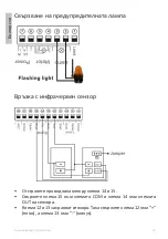
Electrical components installation diagram
»
Terminals 6 and 7 are for 230V connection
Содержание AP800C
Страница 2: ......
Страница 15: ...15...
Страница 16: ...16 2 x 2 1 6 1 1 x...
Страница 17: ...17 26 C 80 C 230V 350W M 4 30 0 N m 12 1400 1100N 800 50 m 2...
Страница 18: ...18 10A 35 1 4 2 4...
Страница 19: ...19 2 3 mm...
Страница 20: ...20 10A 1...
Страница 21: ...21 13 1 Paring the remote control LEARN 13 1 D5 10 D5 D5 10 LEARN 6 D5 20 D5 5 1 2 1 2 3 4...
Страница 23: ...23 10 8 ON 6 ON 30 2 4 2 4 2 4 5 10 30 2 4 7 ON 13 4...
Страница 24: ...24 13 5 LED D1 LED D2 LED D3 LED D4 D6 D7 D8 LED 13 6 2 13 7 J1 J1 13 6 Jumper J1 1 NO1 NO2 2 NO2 NO3...
Страница 25: ...25 6 7 230V 3 4 5 4 5 3 4 5 3...
Страница 26: ...26 14 15 15 COM 14 OUT 12 13 12 13...
Страница 27: ...27 NO NO 11 10 11 12 13 3...
Страница 28: ...28...
Страница 133: ......
Страница 134: ......


