7
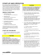
START-UP AND OPERATION
The non-cycling design of the refrigerated dryer assures
proper dew point control at all load conditions. The
refrigerant compressor runs continuously when the dryer
is “ON”. All dryers are installed with fan cycling switches.
These fans will cycle with respect to the load changes,
ambient temperature fluctuations, and the cleanliness of
the condenser. Standard units are designed to operate
under the following conditions:
DESIGN CONDITIONS
1.
Inlet Air Temperature:
100°F (38°C) design 120°F (49°C)maximum
2.
Inlet Air Pressure:
100 PSIG design 150 PSIG maximum
3.
Ambient Air Temperature:
55°F (13°C) minimum 100°F (38°C) maximum
4.
Cooling Water Temperature:
90°F (32°C) maximum
5.
Cooling Water Pressure:
35 PSIG minimum 100 PSIG maximum
At temperatures above the 100°F (38°C) design,
refrigeration capacity will decrease. Operating air
pressures below the 100 PSIG design will reduce
system capacity.
START-UP PROCEDURE
1. If the suction pressure gauge reads zero, refrigerant
loss has occurred. Call the factory or distributor for
service.
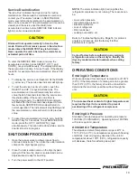
CAUTION
CRANKCASE HEATER
Air dryers with three-phase power supply are
equipped with a compressor crankcase heater. This
heater must be energized by closing the disconnect
switch a minimum of 6 to 10 hours before start-up.
Power to the air dryer can be left on to energize the
crankcase heater for off-cycle, during evening or
weekend shutdowns (except scroll compressors).
CAUTION
STARTING THE DRYER WITHOUT ENERGIZING THE
CRANKCASE HEATER WILL CAUSE PREMATURE
FAILURE OF THE REFRIGERANT COMPRESSOR.
Failure to comply with procedure of energizing
crankcase heater before start-up may void warranty.
2. Check the temperature on the crankcase of the
compressor to make sure the crankcase heater is
working before starting the dryer.
3. For water-cooled Air Dryers (ADW) make sure the
water supply (Minimum Pressure 35 PSIG) is
available at the condenser inlet. The water
regulating valve will modulate and control the water
flow with respect to the dryer load conditions. The
water-cooled condenser drain plug (located inside
enclosure) must be installed.
4. For open frame design units [Models AD(W)-1500 &
larger], the following valves
must be open
prior to
start-up. All valves are tagged with specific
instructions.
a. Compressor isolation valves (suction &
discharge service valves).
b. Receiver valve(s) (air-cooled models only).
c. Condenser outlet liquid line valve (water-cooled
models only).
d. Hot gas line valve – Models AD(W)-2500 &
larger. Located on the hot gas line before the Hot
Gas Bypass Valve.
e. Liquid line valve on water-cooled condenser
outlet (water-cooled models only).
5. Turn the power ON/OFF switch to the ON position.
6. The suction pressure will gradually come down to
the blue or green range depending on the type of
refrigerant used in the air dryer. Check the
refrigerant suction pressure gauge reading. If the
suction pressure is above or below the suggested
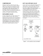
color range, a hot gas bypass valve adjustment is
required. (Refer to the Hot Gas Bypass Valve
section of this manual.) For proper operating range
and control settings see listing below.
Содержание AD Series
Страница 1: ...Noncycling Refrigerated Air Dryers AD 750 to 4000 Series Owner s Manual 9829 2103 73 August 2009 ...
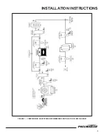
Страница 5: ...INSTALLATION INSTRUCTIONS 4 FIGURE 1 COMPRESSED AIR SYSTEMS RECOMMENDED INSTALLATION FLOW DIAGRAM ...
Страница 15: ...14 FIGURE 6 FLOW DIAGRAM AD 750 to 1000 ...
Страница 16: ...15 FIGURE 7 FLOW DIAGRAM AD 1200 to 2000 ...
Страница 17: ...FIGURE 8 FLOW DIAGRAM AD 2500 to 4000 16 ...
Страница 22: ...21 ...
Страница 23: ...22 ...
Страница 24: ...Pneumatech 4909 70th Avenue Kenosha WI 53144 Phone 262 658 4300 Fax 262 658 1945 www pneumatech com ...


