


Cardox Techical Manual
Page 16
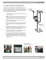
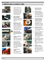
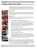
8.40 A regular filled tube needs to be placed firmly into that hole. This can be accom
-
plished by using a #5790-0031 Adapter CDX that is threaded into the Pneumat
fill head and connects extension drill shafts (#5300-0013) to the tube. An eyebolt
#5731-0004 can be used to connect the shafts to the cable wench for securing the
assembly to the silo.
8.41 Place the tube tightly in the drilled hole and secure the assembly. Since this is a
“cold” application there is no concern with the time in the material and no concern
about having the fill head into the vessel.
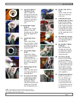
8.42 The firing cables should be taped with electrical tape to hold them in the fill head as
the assembly is extended deeper into the vessel.
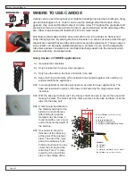
8.43 Place the assembly in the silo and properly secure that assembly in place. Move to
the opposite end of the firing cable, which should be around a corner or out of the
line of the tube direction by 25’ – 30’. Hook up the MHSA approved blaster.
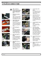
8.44 Observe that the area around the blast is secured. Hold the left button down on the
blaster until the red light comes on. Continue to hold the left button with the light on
and depress the right button to activate the safety heater inside the tube.
8.45 The blast should occur immediately. Once the blast has occurred remove the
blaster and re-shunt that end of the firing cables.
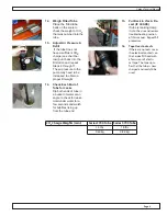
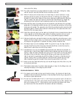
8.46 If a blast does not occur, immediately approach the tube. Observe the location of
the relief hole in the fill head. Make certain that the relieved gas will not strike you
in the face. Open the safety bleeder valve using a 1/4” hex wrench. Let the gas
bleed off before removing the tube completely. Relieving this pressure will cause
the inside of the tube to go back to equal pressure with the outside. The heater in
the tube cannot function unless it has a constant pressure around it that is greater
than 275 PSI. After relieving the gas from inside of the tube will be less than the
275 PSI.
8.47 Remove the tube.
8.48 This failed to blast tube should be marked properly or take it to the filling room and
carefully dismantle it according to section #6.03
Safety Recap
9.00 Remember to respect the Cardox tube. When properly filled it will have 4000-5000
PSI of pressure inside the tube. When it is activated it will exhaust out of the dis-
charge end at 27,000-30,000 PSI.
9.01 CO2 is heavier than normal air, therefore there should be a vent located near the
floor or in the floor of the filling room.
9.02 To have success with the Cardox system the tube must be filled with liquid CO
2.
CO2 is always trying to get to its gas state. As it passes from liquid to gas, it goes
through a solid dry ice state and makes metal surfaces very cold. Gloves should be
used when handling tubes that have CO2 released from inside.
9.03 When there is a failed activation the safety bleeder screw should be opened before
removing the tube from the base port.
Содержание Cardox CO2
Страница 1: ...A B C D 8 7 6 TECHNICAL MANUAL 110 Mohr Drive Mankato MN 56001 1 800 458 9446 www pneumat com ...
Страница 22: ...Cardox Techical Manual Page 22 5780 0005 Cardox Fill Stand Assembly Parts List ...
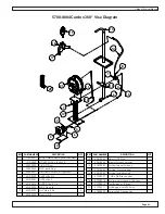
Страница 25: ...Cardox Techical Manual Page 25 5730 0003 Auto Fill Activating Head w Eyebolt Parts List ...
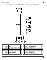
Страница 27: ...Cardox Techical Manual Page 27 Series 3700 Firing Head Tube Body Discharge Head Parts List ...
Страница 28: ...Cardox Techical Manual Page 28 Series 5700 Firing Head Tube Body Discharge Head Parts List ...


