010219/0 ControlPro/Diluter
EN - 8
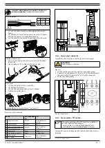
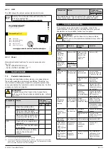
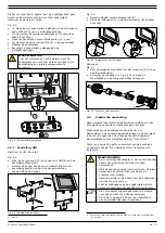
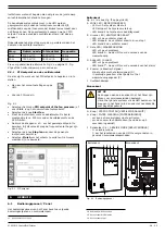
• Put the motor cable (A) through the left cable gland.
• Put the PTC cable (B) through the middle cable gland.
Fig. 4.9
A
B
Motor cable and PTC cable
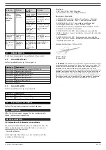
To connect the motor cable and the PTC cable to the VFD
(frequency inverter), do the following.
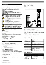
Fig. 4.9 + Fig. 4.12 (electrical diagram)
Connection of the motor cable to the VFD
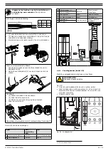
• Remove the front cover (lower part) of the VFD inside the
Panel.
• Remove the outer insulation from the motor cable at the
position of the EMC clamp (A).
• Connect the motor cable in accordance with the electrical
diagram.
• Fasten the EMC clamp.
Fig. 4.10
PE
A
Motor cable to VFD
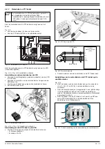
Fig. 4.11 + Fig. 4.12 (electrical diagram)
Connection of the PTC cable to the VFD
• Connect the PTC cable in accordance with the electrical
diagram.
- A: screwdriver
- B: wires 13+33
Fig. 4.11
B
A
PTC cable to VFD
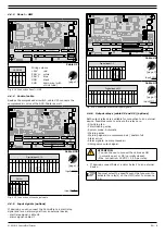
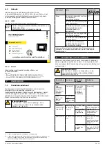
Fig. 4.12
Control box
(CB-PMD)
Control box
(CB-PMD)
System control
panel (SCP)
M
3 Ø
L1 L2 L3
13
33
U 96
V 97
W 98
53
13
53
13
99 (PE)
X3.9-10
X3.11-12
X3.13-14
X1.5-6 solenoid
V1
5
PE
6
X3.1-2
X3.3-4
X3.5-6
X3.7-8
X1.7-8 solenoid
X1.3-4 (compressed air)
X1.1-2 ∂P filter
X1.5-6 solenoid
X1.7-8 solenoid
X1.3-4 (compressed air)
X1.1-2 ∂P filter
PTC cable
PMD cable
VFD
VFD
Mains cable
PT cable
Solenoid cable
Pressure transmitter
(PT-1000)
Main switch
Mains
motor cable
PMD cable
System control
panel (SCP)
V1
5
PE
6
V2
7
PE
8
Solenoid cable
X3.9-10
X3.11-12
X3.13-14
X3.1-2
X3.3-4
X3.5-6
X3.7-8
VFD
53
12
X
1 2
P-
P+
PTC cable
Danfoss
frequency inverter
(VFD)
motor cable
M
3 Ø
13
33
U 96
V 97
W 98
99 (PE)
PT cable
Electrical diagram
• Fasten the cable glands of the motor cable and the PTC
cable.
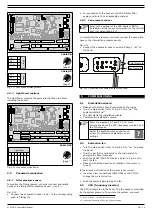
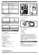
Connection of the motor cable and the PTC cable to the
fan motor
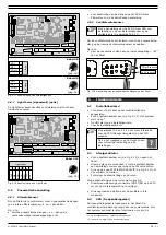
• Connect the wires of the motor cable to the connectors U1,
V1, W1 (C) and PE (A) in the junction box of the fan.
• Connect the metal plates (supplied in a plastic bag within
the junction box) to obtain a “delta” connection. Make sure
that the connection is in accordance with the motor plate.
• Connect the wires of the PTC cable (incl. shield to PE) to
the PTC connection (B) in the junction box. This connection
is
not
phase sensitive.
Fig. 4.13
B
C
A
“Delta” connection of the motor cable to the fan motor
Содержание CONTROLPRO/DILUTER
Страница 40: ...www plymovent com 010219 0 ControlPro Diluter ...

