


010219/0 ControlPro/Diluter
EN - 11
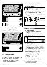
know or determine the airflow in the duct that is necessary to
get the correct throw and air circulation.
The required system pressure must be programmed in the HMI
to keep the airflow at a constant level, independently from the
(increasing) pressure drop caused by the filter cartridges. This
system pressure is called the ‘PID setpoint’, which arranges
the necessary fan speed (Hz) accordingly.
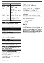
The table below indicates the throw related to the airflow and
fan speed
13
.
Throw
Airflow/
nozzle
Total airflow Frequency
20 m (65 ft)
1000 m�/h
(590 CFM)
6000 m�/h
(3530 CFM)
30 Hz
40 m (130 ft)
1500 m�/h
(885 CFM)
9000 m�/h
(5300 CFM)
50 Hz
For more detailed information, refer to Fig. V on page 37.
Fig. VI shows the horizontal throw per nozzle.
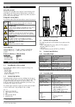
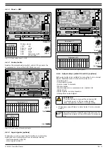
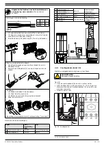
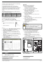
5.3.1 PID setpoint of the fan pressure
To determine and set the PID setpoint, do the following.
• Go to the Settings menu on the HMI.
• Enter PIN.
• Select menu
PID setpoint of the fan pressure
(or enter
2.2.1
on the numeric keypad).
• Select the button
Start fan
.
•
Measure the actual airflow with a flowmeter. Best
measuring position: approx. 500 mm (20 in.) below the
outlet unit of the SCS-Diluter.
• Use the buttons
+
or
─
to determine the setpoint to reach
the desired airflow. At this setpoint, the frequency must
not exceed 45Hz.
• Select
Stop fan
when the desired airflow is reached.
• Select
Finish
to exit the screen. The new values will be
saved.
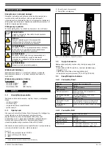
Fig. 5.1 PID setpoint
6
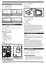
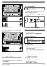
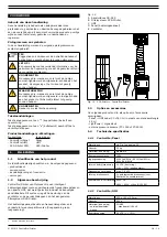
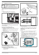
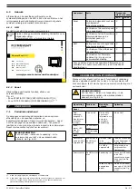
USE
6.1
Control panel / Panel
The control panel contains the following controls and
indicators:
13. All nozzles 100% open
Outside
Fig. 6.1 (also refer to Fig. II on page 36)
A White LED | POWER ON
- LED
off: system is off
- LED blinking: system is starting up
- LED on: system is ready
B Green LED | FAN RUNNING
-
LED off: fan is off
- LED blinking: fan is ramping down
14
- LED on: fan is running
C Yellow LED | WARNING
-
LED off: no problem
- LED on
15
: refer to the HMI for the cause of the warning
D Red LED | ALARM
-
LED off: no problem
- LED on
16
: refer to the HMI for the cause of the alarm
E Buzzer | acoustic signal
- together with the ALARM signal (D)
- in some cases: together with the WARNING signal (C)
F Main switch
Inside
ATTENTION
The buttons inside the Panel are for service
purposes only. You can control the entire system via
the HMI, therefore, the buttons inside the Panel are
not necessary for daily use.
G Button | START/STOP FAN
H Button | FILTER CLEANING
-
to activate an additional filter cleaning cycle
- to suppress the buzzer (push and hold for 5 seconds)
I Switch 0-1 | SERVICE MODE
- 0: normal mode
- I: to lock the touch screen of the HMI for service
purposes
Outside
Inside
C
A
B
A B
D
C
E
F
G H
I
C
A
B
A B
D
C
E
F
G H
I
Fig. 6.1 Control panel
6.2
Use
Depending on the specific configuration and system settings
on the HMI, you can activate the fan and cleaning system
manually or have the entire system run fully automatically.
14. Ramp down time: 60 seconds
15. The system continues to run
16. The system stops running
Содержание CONTROLPRO/DILUTER
Страница 40: ...www plymovent com 010219 0 ControlPro Diluter ...


