010219/0 ControlPro/Diluter
EN - 10
Indicator LED’s
Valves
Dustbin
sensor
Fan Pressure
sensor
Digital input 1-5
RS485 VFD
CAN Slave
CAN HMI
Digital input 6-12
Filter Pressure
sensor
Analog
output
Light tower
Power
Rel
ay
s 1
Rel
ay
s 2
Cable #8
Indicator LED’s
Valves
Dustbin
sensor
Fan Pressure
sensor
Digital input 1-5
RS485 VFD
CAN Slave
CAN HMI
Digital input 6-12
Filter Pressure
sensor
Analog
output
Light tower
Power
Rela
y 1
R
ela
y 2
Ethernet
(for service only)
USB
(firmware updates)
RS-232
(for service only)
Filter pressure
(internal sensor)
Fan pressure
(internal sensor)
+
-
+
-
Valves
1
+ 24V
2
OUT 1
3
GND
4
+ 24V
5
OUT 2
6
GND
Indicator LED’s
1
+ 24V
2
PWR
3
RUN
4
ALA
5
WRN
6
+ 24V
7
BUZ
Dustbin
sensor
1
+ 24V
2
IN 1
3
GND
4
SHD
Fan Pressure
sensor
1
+ 24V
2
IN 2
3
GND
4
SHD
Analog
output
1
OUT
2
GND
3
SHD
Digital input 1-5
1
+ 24V
2
IN 1
3
+ 24V
4
IN 2
5
+ 24V
6
IN 3
7
+ 24V
8
IN 4
9
+ 24V
10
IN 5
11
COM1
12
GND
Digital input 6-12
1
+ 24V
2
IN 6
3
+ 24V
4
IN 7
5
+ 24V
6
IN 8
7
+ 24V
8
IN 9
9
+ 24V
10
IN 10
11
+ 24V
12
IN 11
13
+ 24V
14
IN 12
15
COM2
16
GND
CAN Slave
1 2
CAN_H
3
CAN_L
4
GND
5
SHD
+ 24V
Power
+ 24V
2
GND
1
1 2
A
3
B
4
GND
5
SHD
RS485 VFD
8
1
NO 1
2
NC 1
3
COM 1
4
5
NO 2
6
NC 2
7
COM 2
Light tower
1
+ 24V
2
PWR
3
RUN
4
ALA
5
WRN
6
+ 24V
7
BUZ
Filter Pressure
sensor
1
+ 24V
2
IN 3
3
GND
4
SHD
CAN HMI
1 2
CAN_H
3
CAN_L
4
GND
5
SHD
+ 24V
8
Rela
y 1
R
ela
y 2
IN 5 External start/stop signal
IN 6 Fire alarm (ShieldControl)
IN 7 Sliding valve feedback 1
IN 8 Sliding valve feedback 2
IN 9 Fan alarm
IN 10 Compressed air switch
IN 11 External alert
IN 12 Dustbin level switch
SCS
:
cleaning v
alv
es (1 or 2)
MDB
: (only f
or ShieldC
on
tr
ol)
- out1
sliding v
alv
es
- out2
c
onpr
essed air r
elease
IN 1 BTN start/stop fan
IN 2 BTN filter cleaning
IN 3 Service mode switch
IN 4 Spare
Cable #9
Indicator LED’s
Valves
Dustbin
sensor
Fan Pressure
sensor
Digital input 1-5
RS485 VFD
CAN Slave
CAN HMI
Digital input 6-12
Filter Pressure
sensor
Analog
output
Light tower
Power
Rela
y 1
R
ela
y 2
Ethernet
(for service only)
USB
(firmware updates)
RS-232
(for service only)
Filter pressure
(internal sensor)
Fan pressure
(internal sensor)
+
-
+
-
Valves
1
+ 24V
2
OUT 1
3
GND
4
+ 24V
5
OUT 2
6
GND
Indicator LED’s
1
+ 24V
2
PWR
3
RUN
4
ALA
5
WRN
6
+ 24V
7
BUZ
Dustbin
sensor
1
+ 24V
2
IN 1
3
GND
4
SHD
Fan Pressure
sensor
1
+ 24V
2
IN 2
3
GND
4
SHD
Analog
output
1
OUT
2
GND
3
SHD
Digital input 1-5
1
+ 24V
2
IN 1
3
+ 24V
4
IN 2
5
+ 24V
6
IN 3
7
+ 24V
8
IN 4
9
+ 24V
10
IN 5
11
COM1
12
GND
1
+ 24V
2
IN 6
3
+ 24V
4
IN 7
5
+ 24V
6
IN 8
7
+ 24V
8
IN 9
9
+ 24V
10
IN 10
11
+ 24V
12
IN 11
13
+ 24V
14
IN 12
15
COM2
16
GND
CAN Slave
1 2
CAN_H
3
CAN_L
4
GND
5
SHD
+ 24V
Power
+ 24V
2
GND
1
1 2
A
3
B
4
GND
5
SHD
RS485 VFD
8
1
NO 1
2
NC 1
3
COM 1
4
5
NO 2
6
NC 2
7
COM 2
Light tower
1
+ 24V
2
PWR
RUN
4
ALA
5
WRN
6
+ 24V
7
BUZ
Filter Pressure
sensor
1
+ 24V
2
IN 3
3
GND
4
SHD
CAN HMI
1 2
CAN_H
3
CAN_L
4
GND
5
SHD
+ 24V
8
Rela
y 1
R
ela
y 2
IN 5 External start/stop signal
IN 6 Fire alarm (ShieldControl)
IN 7 Sliding valve feedback 1
IN 8 Sliding valve feedback 2
IN 9 Fan alarm
IN 10 Compressed air switch
IN 11 External alert
IN 12 Dustbin level switch
SCS
:
cleaning v
alv
es (1 or 2)
MDB
: (only f
or ShieldC
on
tr
ol)
- out1
sliding v
alv
es
- out2
c
onpr
essed air r
elease
IN 1 BTN start/stop fan
IN 2 BTN filter cleaning
IN 3 Service mode switch
IN 4 Spare
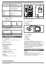
Fig. 4.17 Connection of relay outputs
4.4.7 LightTower (option)
The LightTower contains the same pilot lights as the Panel,
including the buzzer.
Indicator LED’s
Valves
Dustbin
sensor
Fan Pressure
sensor
Digital input 1-5
RS485 VFD
CAN Slave
CAN HMI
Digital input 6-12
Filter Pressure
sensor
Analog
output
Light tower
Power
Rela
ys
Cable #22
Indicator LED’s
Valves
Dustbin
sensor
Fan Pressure
sensor
Digital input 1-5
RS485 VFD
CAN Slave
CAN HMI
Digital input 6-12
Filter Pressure
sensor
Analog
output
Light tower
Power
Rela
y 1
R
ela
y 2
Ethernet
(for service only)
USB
(firmware updates)
RS-232
(for service only)
Filter pressure
(internal sensor)
Fan pressure
(internal sensor)
+
-
+
-
Valves
1
+ 24V
2
OUT 1
3
GND
4
+ 24V
5
OUT 2
6
GND
Indicator LED’s
1
+ 24V
2
PWR
3
RUN
4
ALA
5
WRN
6
+ 24V
7
BUZ
Dustbin
sensor
1
+ 24V
2
IN 1
3
GND
4
SHD
Fan Pressure
sensor
1
+ 24V
2
IN 2
3
GND
4
SHD
Analog
output
1
OUT
2
GND
3
SHD
Digital input 1-5
1
+ 24V
2
IN 1
3
+ 24V
4
IN 2
5
+ 24V
6
IN 3
7
+ 24V
8
IN 4
9
+ 24V
10
IN 5
11
COM1
12
GND
Digital input 6-12
1
+ 24V
2
IN 6
3
+ 24V
4
IN 7
5
+ 24V
6
IN 8
7
+ 24V
8
IN 9
9
+ 24V
10
IN 10
11
+ 24V
12
IN 11
13
+ 24V
14
IN 12
15
COM2
16
GND
CAN Slave
1 2
CAN_H
3
CAN_L
4
GND
5
SHD
+ 24V
Power
+ 24V
2
GND
1
1 2
A
3
B
4
GND
5
SHD
RS485 VFD
8
1
NO 1
2
NC 1
3
COM 1
4
5
NO 2
6
NC 2
7
COM 2
Light tower
1
+ 24V
2
PWR
3
RUN
4
ALA
5
WRN
6
+ 24V
7
BUZ
Filter Pressure
sensor
1
+ 24V
2
IN 3
3
GND
4
SHD
CAN HMI
1 2
CAN_H
3
CAN_L
4
GND
5
SHD
+ 24V
8
Rela
y 1
R
ela
y 2
IN 5 External start/stop signal
IN 6 Fire alarm (ShieldControl)
IN 7 Sliding valve feedback 1
IN 8 Sliding valve feedback 2
IN 9 Fan alarm
IN 10 Compressed air switch
IN 11 External alert
IN 12 Dustbin level switch
SCS
:
cleaning v
alv
es (1 or 2)
MDB
: (only f
or ShieldC
on
tr
ol)
- out1
sliding v
alv
es
- out2
c
onpr
essed air r
elease
IN 1 BTN start/stop fan
IN 2 BTN filter cleaning
IN 3 Service mode switch
IN 4 Spare
Fig. 4.18 Connection of LightTower
4.5
Pneumatic connection
4.5.1 Filter pressure sensor
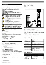
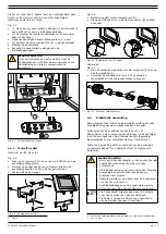
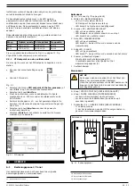
To monitor the filter pressure, you must connect pneumatic
hoses to the internal filter pressure sensor (+ and –).
• Connect the pneumatic hoses + and – to the corresponding
push-in fittings (A).
•
For connection of the hoses to the SCS-Diluter filter
system, refer to the corresponding manual.
4.5.2 Fan pressure sensor
Refer to the manual of the SCS-Diluter PRO for
installation of the fan pressure sensor to the vertical
duct (ref. paragraph 4.4.11).
To monitor the fan pressure, you must connect the pneumatic
hose to the internal fan pressure sensor.
•
Connect the pneumatic hose to push-in f (B)
11
on
the Panel.
Fig. 4.19
B
Filter –
Fan +
Filter Pressure
+
+
―
Fan Pressure
B
A
Connection of pneumatic hoses to the Panel
5
COMMISSIONING
5.1
Installation wizard
• Make sure that the Panel is connected to the mains.
• Turn the main switch (refer to Fig. 6.1F) to “
on
”. The
system will start up
12
.
• The HMI starts the installation wizard.
• Complete the installation wizard.
Refer to paragraph 5.3 and 5.3.1 for more
information about the VFD (frequency inverter) and
the PID setpoint.
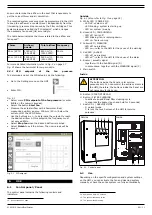
Select the question mark on the touch
screen for extensive explanation on all
settings.
?
5.2
Extraction fan
• Turn the main switch (refer to Fig. 6.1F) to “
off
” and open
the Panel.
• Turn the bar that is connected to the main switch to
energize the Panel manually.
• Push the START/STOP FAN button (refer to
start the fan.
• Make sure that the direction of rotation of the motor is
correct.
If the direction of rotation of the motor is not correct:
• Invert any two connections (96/97/98) on the VFD to
change the motor direction.
• Push the button again to stop the fan.
5.3
VFD (frequency inverter)
The VFD is integrated in the Panel. The fan speed is controlled
by the system pressure. To operate the system, you must
11.
Push-in fitting – (minus) remains unused
12. Indication: the white LED on the Panel is blinking
Содержание CONTROLPRO/DILUTER
Страница 40: ...www plymovent com 010219 0 ControlPro Diluter ...

