


010219/0 ControlPro/Diluter
EN - 5
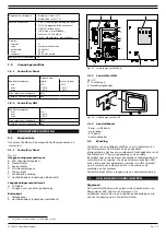
4.1.1 To be sourced locally
Mounting material
5
:
- to install the Panel to the fan housing or to the wall
(hardware max. Ø 10 mm)
- to install the HMI to the wall (head height of screws max. 6
mm, Ø max. 4 mm)
Connection cables
6
:
on page 38 for the cable specifications
If necessary:
- additional cable glands M16
Optional (for remote access to HMI via network):
- ethernet cable, min. CAT 5E shielded
4.2
Unpacking
For the complete scope of supply, refer to the manual
SCS-Diluter.
4.3
Mounting
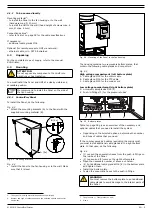
ATTENTION
Do not expose any component of ControlPro to
vibrations or heat radiation.
You must install the Panel and HMI at a clearly visible and
accessible position.
We recommend to install the Panel on the side of
the fan housing.
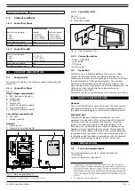
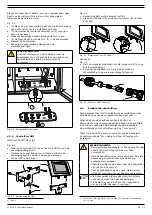
4.3.1 ControlPro/Panel
To install the Panel, do the following.
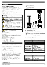
• Attach the mounting brackets (A) to the Panel with the
supplied mounting material (B).
Fig. 4.3
B (4x)
A (4x)
Mounting brackets
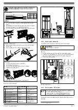
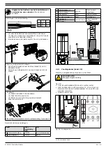
• Install the Panel to the fan housing or to the wall. Make
sure that it is level.
5. The type of mounting material depends on the wall type
6. Number and type of cables depend on the selected options and control
equipment
Fig. 4.4
B (4x)
A (4x)
Mounting of the Panel to the fan housing
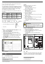
The housing contains two removable bottom plates, that
contain the following cable glands and connectors:
High voltage compartment (left bottom plate)
A Cable gland M25 for the motor cable
B Cable gland M16 for the PTC cable
C Cable gland M25 for the mains cord
Low voltage compartment (right bottom plate)
D Universal cable glands M16 (4)
E
Push-in fittings (3) for the pressure tubes
7
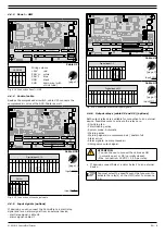
Fig. 4.3
A
B
C
D
E
Bottom plates
on page 38 gives an overview of the necessary and
optional cables that you need to install the system.
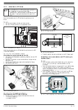
• Depending on the selected options, determine the number
and type of cables that you need.
If the number exceeds 4 cables (excluding the mains cord),
you must install additional cable glands in the right bottom
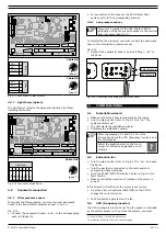
plate. In that case, do the following.
•
(1) Loosen the pneumatic hoses from the push-in fittigs on
the inside of the Panel.
• (2) Loosen and (3) remove the right bottom plate.
• Open the necessary number of knock-out holes
8
.
• (4) Put additional cable glands M16 (E) in the bottom plate
and tighten them.
• Install the bottom plate.
•
Fasten the pneumatic hoses to the push-in fittigs.
WARNING
You must remove the bottom plate to put additional
cable glands to avoid damage to the interior parts of
the Panel.
7. Fan pr | Filter pr and –
8. Max. 4
Содержание CONTROLPRO/DILUTER
Страница 40: ...www plymovent com 010219 0 ControlPro Diluter ...


