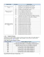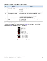
3.2.2
PCI Express Lane 0 to Lane 3
PCI Express lanes 0 - 3 of PEX 8619 are routed to the receptacle U74 as shown in
. When Configuration
Module 0108 is plugged into U74 at Case (a), lanes 0-3 will be separately connected with a single line going to
the following: PCI Express cable connector J5, PCI Express SLOT 1, PCI Express SLOT 2 and PCI Express
SLOT 3. This results in x1 links to form port 0, 4, 6, and 8. When Configuration Module 0107 is plugged into U74
at Case (b), all four lanes will be connected to x4 PCI Express cable connector J5 to form a x4 link at port 0. Note
that the PCIe signals to PCIe Cable Connector J5 can be an independent x4 port or the lower lanes of a x8 port.
x16 P
C
I Express Con
necto
rs
Port 0
x1link to upstream
SLT3
SL2
SLT1
4x PCIe
Cable
Connector
J5
Configuration Module
0108
Lane 0
Lane 1
Lane 2
Lane 3
Port 8 Port 6 Port 4
Lane 0-3
x16 P
C
I Express Con
necto
rs
Port 0
x4 link or lower 4 lanes
of x8 link to upstream
SLT3
SL2
SLT1
Configuration Module
0107
Lane 0-3
Lane 0-3
4x PCIe
Cable
Connector
J5
U74
U74
PEX 8619
(U100)
Lane 3-0
Lane 8-11
La
ne 4-7
Lan
e 12-1
5
A1
A1
PEX 8619
(U100)
Lane 3-0
Lane 8-11
Lane
4-7
L
ane 12-
15
(a)
(b)
Figure 4. Lanes 0-3 Hardware Connections on the RDK
3.2.3
PCI Express Lane 4 to Lane 7
PCI Express lanes 4-7 of PEX 8619 are routed to the receptacle U75 as shown in
. When Configuration
Module 0108 is plugged into U75 at Case (a), lanes 4-7 will be separately connected to PCI Express SLOT 4 to
SLOT 7 with x1 link each to form ports 2, 10, 12, and 14. When Configuration Module 0107 is plugged into U75 at
Case (b), four lanes will be connected to SLOT 4 to form a x4 link (port 4). When Configuration Module 0109 is
plugged into U75 lane 4-7 will be connected to PCI Express cable connector J6 to form the upper four lanes of
port 0 when port 0 is configured as a x8 port.
PEX 8619BA Base Board RDK Hardware Reference Manual – Version 1.0
Copyright © 2008 by PLX Technology, Inc. All rights reserved
6


