background image


6


STEP3: 

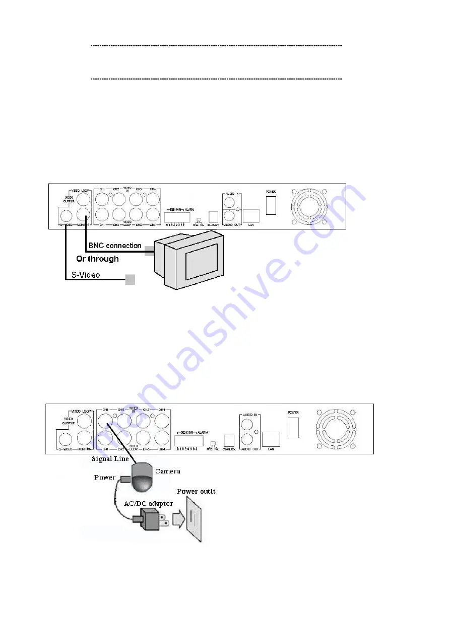
Please connect TV (monitor) to the Video output connector in the rear panel.   


Video Input connection (TV or monitor)


STEP4: 

Please use standard analog video cameras to connect to the DVR400. The DVR-400 equipped 4 

BNC connectors on the rear panel for video input.


Physical camera installation with DVR-400 is shown as below: 

Connect the camera signal line to video input on DVR-400 

Power on camera, and you may now check the video on the screen.


DVR-400 provides 4 x BNC connectors for video source input


ë

Note


Please be sure to finish the hard disk drive installation 
before using the DVR. The Maximum HDD capacity support is 
250GB. 

ë

Note


DVR-400 provides one S-Video and two BNC connector for video 

output.


Содержание DVR-400

Страница 1: ...1 Digital Video Recorder DVR 400 User s manual...

Страница 2: ...o responsibility for any inaccuracies that may be contained in this User s Manual PLANET makes no commitment to update or keep current the information in this User s Manual and reserves the right to m...

Страница 3: ...3 Revision User s Manual for PLANET Digital Video Recorder Model DVR 400 Rev 1 0 Oct 2004 Part No EM DVR400V1...

Страница 4: ...3 DVR 400 Menu Setup 12 Introduction 12 MAIN MENU 12 CAMERA SELECT 13 RECORD SELECT 14 VIDEO RECORDING MODE 14 RECORD FRAMRATE 15 VIDEO QUALITY 16 RECORD SCHEDULE 17 SUB MENU 18 PASSWORD CHANGE 18 TIM...

Страница 5: ...lowing operation guide explains how to operate manage the DVR 400 and the following installation guide explains how to complete the first DVR 400 installation on your side DVR Functions High quality M...

Страница 6: ...adapter Screws for swappable HDD tray Keys for swappable HDD tray Quick installation guide User s manual CD Physical Details Front Panel of DVR 400 Rear Panel of DVR 400 Buttons Definitions The follow...

Страница 7: ...ack backward CHANNEL 1 press to select video source on channel 1 CHANNEL 2 press to select video source on channel 2 CHANNEL 3 press to select video source on channel 3 CHANNEL 4 press to select video...

Страница 8: ...tputs provide loop through connections and can be used for direct monitoring of the connected video cameras 6 Sensor input alarm output 4 sensor inputs and one alarm output 7 NTSC PAL switch 8 DC in 1...

Страница 9: ...isk tray cover connect your harddisk securely with the DC power cable and IDE cable in the harddisk tray Make sure the installed HDD is set to Master and secure the HDD using the original HD screws or...

Страница 10: ...ideo input Physical camera installation with DVR 400 is shown as below l Connect the camera signal line to video input on DVR 400 l Power on camera and you may now check the video on the screen DVR 40...

Страница 11: ...cator should be Green during normal operation After powering on the DVR 400 it will check HDD for several seconds the information will be displayed on the monitor After the internal checking completed...

Страница 12: ...plug in the adaptor Alarm installation The unit provides 1 internal switch for sounding alarm when the sensor is activated due to the unwanted entrance of anonymous visitor The switch is open at norma...

Страница 13: ...o exit the menu Press n button to stop playback Press button to start SEARCH TIME HDD DRIVE MASTER 04 03 24 13 24 21 04 03 24 13 44 54 01 TIME 04 09 24 13 24 21 02 TIME 04 09 24 13 30 55 03 TIME 04 09...

Страница 14: ...CT 1234 RECORD MODE EACH RECORD FRAMERATE 30 VIDEO QUALITY MORRMAL RECORD SCHEDULE SUB MENU HARD DRIVE SETUP SENSOR SETUP NETWORK SETUP PRESS THEN SELECT PRESS MENU TO EXIT NETWORK MENU ACCEPT CLIENT...

Страница 15: ...BNET MASK LAN mask of DVR 400 Default 255 255 255 000 GATEWAY Gateway of DVR 400 Default 192 168 000 254 Note In the first installation it is suggested to locate your PC in the same network segment 19...

Страница 16: ...elow figure Operation Buttons Press to display menu option pq Press to change menu field or change the unit s configuration values 8 Press to select menu item or confirm the selection 3 MAIN MENU CAME...

Страница 17: ...ull screen format of each channel Channel 1 button Full screen display of channel 1 Channel 2 button Full screen display of channel 2 Channel 4 button Full screen display of channel 4 Channel 3 button...

Страница 18: ...en you set to EACH mode you can view the full screen display of one specified channel When you set to QUAD mode quad screen 4 camera will be displayed Please use buttons of front panel to select mode...

Страница 19: ...3 5 10 EACH MODE 4CH 0 25 0 5 0 75 1 1 25 1 75 2 5 3 75 7 5 QUAD MODE 1 2 3 4 5 7 10 15 30 MAIN MENU CAMERA SELECT 1 RECORD SELECT 1 RECORD MODE EACH RECORD FRAMERATE 30 VIDEO QUALITY MORRMAL RECORD S...

Страница 20: ...37H 19H NORMAL 763 382 255 190 152 110 76H 51H 25H QUAD MODE LO 877 438 292 228 175 125 88H 58H 29H The recording hours on 80GB HDD MAIN MENU CAMERA SELECT 1 RECORD SELECT 1 RECORD MODE EACH RECORD FR...

Страница 21: ...this period Recording is off during this duration SETTING EXAMPLE 00 00 7 00 SENSOR RECORDING 07 00 11 00 RECORDING DISABLED 11 00 18 00 RECORDING 18 00 24 00 SENSOR RECORDING PROGRAMMED RECORD TTTTTT...

Страница 22: ...400 will prompt message PASSWORD changed SUB MENU PASSWORD CHANGE TIME SET AUDIO RECORD ON AUDIO MUTE OFF DATE DISPLAY MODE YYYY MM DD PRESS THEN SELECT PRESS MENU TO EXIT CURRENT PASSWORD NEW PASSWO...

Страница 23: ...the recoded video files as well DATE DISPLAY FORMAT DVR 400 provides yyyy mm dd or dd mm yyyy format for time display to meet application demands TIME 04 10 10 12 35 23 PRESS THEN SELECT PRESS MENU TO...

Страница 24: ...the unit formatted the message HARD DISK FORMATTED will appear on the screen SENSOR SETUP SENSOR RECORD TIME Recording duration in seconds when sensor is triggered ALARM OUT TIME The ALARM TIME OUT c...

Страница 25: ...the Motion detection recording in DVR 400 STEP 1 Please go to SENSOR SETUP menu STEP 2 Toggle the motion detection option STEP 3 After the selection please browse to MAIN MENU and go to RECORD SCHEDU...

Страница 26: ...TWORK MENU ACCEPT CLIENT YES MAC ADDRESS 00 30 4F 09 78 52 IP ADDRESS 192 168 000 020 SUBNET MASK 255 255 255 000 GATEWAY 192 168 000 254 PRESS THEN SELECT PRESS MENU TO EXIT Note Minimum requirements...

Страница 27: ...s this button to play the recorded video You can either enter the specified time date to playback or select the event or even view the playback over PC Fast forward button Note The reverse playback sp...

Страница 28: ...Hours 36 Hours 72 Hours 540 Hours NORMAL 24 Hours 48 Hours 96 Hours 720 Hours QUAD screen BASIC 29 Hours 58 Hours 116 Hours 870 Hours HIGH 32 Hours 64 Hours 128 Hours 960 Hours NORMAL 45 Hours 90 Hou...

Страница 29: ...re the video from the unit and play the stored video later on Procedures of DVR Client utility Please find the DVR_Client exe in the Utility folder on user s manual CD Copy the DVR utility folder to s...

Страница 30: ...ord is same password used for formatting the DVR 400 Hard Drive The default value is 111111 When successfully connected you would see Connected sign This window also displays DVR 400 IP address and st...

Страница 31: ...he remote DVR operational button allows you to control remote DVR to live view record and playback as well Capture Playback When you click REC button it will start to record the incoming video on your...

Страница 32: ...reviously captured DVR management This option enable you to just remote DVR s operation setting Video Quality Record Frame rate Alarm On Duration Alarm record Duration Input Channels Record Channels D...

Страница 33: ...0fps NTSC Max 25fps PAL Recording Frame Rate Each mode Max 7 5fps NTSC Max 6 25fps PAL Recording Mode Continuous manual event programed Resolution Display NTSC 720 480 PAL 720 576 Resolution Recording...

Отзывы: