TC160 / TC320
NETWORKING GUIDE
(v.1.8)
www.planckvisionsystems.com
2
Introduction
The ThermaCheck software can communicate with up to four cameras through a network switch. Most
routers have a switchboard of ethernet ports that can be used for this purpose. Since the
default IP
address of each ThermaCheck camera is the same, multiple cameras must be added sequentially to
the network with each camera being reassigned a unique IP address. The steps required to do this are
described in Section 3.
Multi-camera network
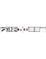
The multi-camera network, as illustrated in Figure 1, consists of:
1.
One computer running the ThermaCheck Software
2.
A switchboard of ethernet ports, one port for the computer and an additional port for each
ThermaCheck camera.
3.
One to four ThermaCheck cameras
Figure 1: Multi-camera network
Steps for adding each new camera to the network
Multiple cameras must be added sequentially to the network with each camera being reassigned a
unique IP address. The steps required to do this are as follows.
Step 1
Connect the computer and
one
ThermaCheck camera to the ethernet ports on the switch panel as
shown in Figure 1. The provided USB-to-ethernet adapter may be used between the computer and
the switch panel ethernet ports. Most routers provide a few ethernet switch ports. A larger number
may be obtained by using a switch box.
Step 2
This step configures the IP address of the computer on the local network
1.
Open the computer’s “Settings”
, choose “Network & Internet” and then select “Ethernet”
(Figure1-a). Choose "Change adapter options" (Figure1-b) under related settings.
Computer
ThermaCheck cameras
Camera 1
Network switch
USB-to-
ethernet
adapter