2.5 Connections
28
2.5.4 Connections, Control: RS232 & RS485
With serial control, you can control a whole wall, several walls, and any single display in them.
Connect to the computer
Connect the first cube in the wall to the serial out
port of a computer or another type of controller, such
as a video controller. Connect with computer serial
cable, such as Cat-5, using straight-thru cable.
You will probably need to convert the 9-pin serial port
to RJ45 with an adapter, which you can buy in most
electronic stores.
Connect from the computer or controller to the first
Margay. It doesn’t matter which cube this is.
Connect this first cube’s RS485 Out to the next
cube’s RS485 In.
Start with RS232 and loop all the rest with RS485.
Information about controlling with RS232 is in
4.4 “Controlling Margay with RS232/RS485” on
page 74.
For best results, the RS485 cables should be
twisted pair. The pairs are pins 3 & 6 (signal) and
pins 1 & 2 (ground). CAT5 cable has the correct
twisted pairs.
For very long runs of RS485 cable, it may be neces-
sary to terminate in the last Margay in the string. See
4.4 “Controlling Margay with RS232/RS485” on
page 74.
1
2
3
4
6
7
9
8
5
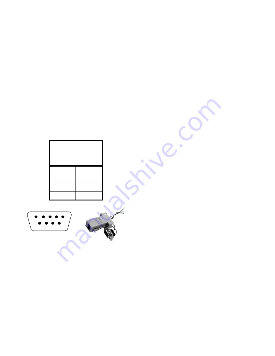
Wiring the adapter
To go from 9-pin D-sub serial connector on the back of
the ccomputer to an RJ45 connector, use a standard
RJ45-to-9-pin adapter. Wire it internally as shown. The
wiring shown for this adapter is correct for
straight-thru
cables. Straight-thru cables are wired 1-to-1, 2-to-2,
etc.
Yellow wire
pin 3
Black wire
pin 2
Green wire
pin 5
RJ45
9-pin
6
3
5
5
3
2
female 9-pin
Содержание WN-5040-720
Страница 1: ...WN 5040 720 User Guide...
Страница 2: ......
Страница 3: ...i WN 5040 720 Margay 50 Display Wall Unit User Guide 020 0548 00B 29 March 2007...
Страница 6: ...iv...
Страница 7: ......
Страница 10: ...1 1 Basic Information About Margay 1 1 Accessories For Margay 2 1 2 Your Safety and Margay s Safety 4...
Страница 14: ...5...
Страница 17: ...6...
Страница 20: ...9...
Страница 24: ...13...
Страница 30: ...19...
Страница 32: ...21 Electronics module as seen from the front The electronics module door is open...
Страница 34: ...23 In Out...
Страница 36: ...25...
Страница 38: ...27 AC power in and out 1 4 5 3 2 6 No more than 4 115 VAC...
Страница 40: ...29...
Страница 51: ...40...
Страница 54: ...43...
Страница 56: ...45...
Страница 58: ...47...
Страница 66: ...55...
Страница 70: ...59...
Страница 72: ...61...
Страница 74: ...63 ENTER ENTER...
Страница 77: ...66...
Страница 80: ...69...
Страница 82: ...71...
Страница 84: ...73...
Страница 86: ...75...
Страница 88: ...77 5 Troubleshooting 5 1 Troubleshooting Tips 78 5 2 Reading the On Screen Code 80 5 3 Reading the LEDs 82...
Страница 95: ...84...
Страница 115: ...104 Diagnostics RS232 RS485 Status...
Страница 116: ...105 Diagnostics Test Patterns...
Страница 117: ...106 Diagnostics Setup Summary...
Страница 128: ...117 Starts scanning the input con nectors for the next available source...
Страница 131: ...120 7 3 Drawings All dimensions are in inches...
Страница 132: ...121...
Страница 133: ...122...
Страница 134: ...123...
Страница 140: ...129...
Страница 144: ...133...
Страница 151: ...140 A B C D E F G H I J K L M N O P Q R S T U W V X Y Z A B C D E F G H I J K L M N O P Q R S T U W V X Y Z...


