Operating the Display
Planar VM Series User Manual
020-1357-01D
Page | 55
18. Tiling Configuration
When using the VM Series displays in a tiled configuration, configure the displays by performing
steps in the following order:
1.
Cabling:
Daisy-chained wiring of video and communication connections. See section
2.
Layout:
Tiled wall size and position of each panel. See section 18.1 (page 55).
3.
Source Configuration:
Selection of the proper input connection on each panel. See
4.
Color Balance:
Adjustment of adjacent displays to ensure that they match in color. See
5.
Frame Compensation:
Adjustment of the tiled image to compensate for the bezel width
and gap between panels. See section 18.3 (page 58).
Note:
This section discusses how to display one image across the entire wall. However, more
complex tiling setup is also possible by configuring the parameters differently for different
subsections of the wall.
18.1 Layout
Configure the following parameters in the Tiling menu (see page 49). These values will be the
same on all displays.
H Monitors:
The number of displays in the horizontal direction on the tiled wall
V Monitors:
The number of displays in the vertical direction on the tiled wall
Additionally, the Position parameter in the Tiling menu will need to be adjusted in each
individual panel. The number represents the location of the panel when counting left-to-right,
top-to-bottom, starting with the top left panel in the wall. Reference the example diagram below
for a 3x4 wall.
H Monitors: 3
V Monitors: 4
Position: 1
H Monitors: 3
V Monitors: 4
Position: 2
H Monitors: 3
V Monitors: 4
Position: 3
H Monitors: 3
V Monitors: 4
Position: 4
H Monitors: 3
V Monitors: 4
Position: 5
H Monitors: 3
V Monitors: 4
Position: 6
H Monitors: 3
V Monitors: 4
Position: 7
H Monitors: 3
V Monitors: 4
Position: 8
H Monitors: 3
V Monitors: 4
Position: 9
H Monitors: 3
V Monitors: 4
Position: 10
H Monitors: 3
V Monitors: 4
Position: 11
H Monitors: 3
V Monitors: 4
Position: 12
Содержание VM Series
Страница 19: ...Package Contents Planar VM Series User Manual 020 1357 01D Page 19 7 Planar VM Series Standard Inputs ...
Страница 34: ...Operating the Display Planar VM Series User Manual 020 1357 01D Page 34 17 OSD Main Menu 17 1 Picture ...
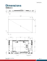
Страница 67: ...Specifications Planar VM Series User Manual 020 1357 01D Page 67 Dimensions VM49LX U ...
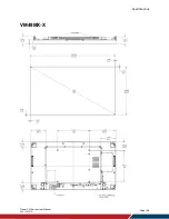
Страница 68: ...Specifications Planar VM Series User Manual 020 1357 01D Page 68 VM49MX X ...
Страница 69: ...Specifications Planar VM Series User Manual 020 1357 01D Page 69 VM55LX M and VM55MX M ...
Страница 70: ...Specifications Planar VM Series User Manual 020 1357 01D Page 70 VM55LX U ...
Страница 71: ...Specifications Planar VM Series User Manual 020 1357 01D Page 71 VM55LX X and VM55MX X ...


