background image

How to Use the OSD Menus


Icon

key Name

Menu

Up

Down

Enter

Power

1. Press the “MENU” button to pop up the “on-screen menu” and press “Up” or “Down” button 
    to select among the 

fi

 ve functions in the main menus.

2. Choose the adjustment items by pressing the “Enter ” button.
3. Adjust the value of the adjustment items by pressing the “Up” or “Down” button.
4. With the OSD menu on screen, press “ Menu” button to return main menu or exit OSD.
5. The OSD menu will automatically close, if you have left it idle for a pre-set time.
6. To Lock the OSD / Power menu buttons, please follow the instructions below.
    (Please note: the monitor has to be turned ON with a valid signal preset)
    (a.) Press “Menu” key , the OSD menu will pops upon display.
    (b.) Press and hold the “Menu” key again with the OSD menu on the screen, the OSD  
          menu will disappear. Then press the “Power” key 1 time while the menu key is still 
          being pressed. The “Lock/Unlock” menu will appear for 3 seconds.
    (c.) Use the “Enter” key to select OSD or Power setting then set at “Lock” by pushing the
          “UP” or “Down” button.
    (d.) When the “UP” or “Down” button is released, the previous setting will be saved and
          exit the “Lock/Unlock” menu automatically.
7. To Unlock the OSD / Power menu buttons, please follow the instructions below.
    (Please note: the monitor has to be turned ON with a valid signal preset)
    (a.) Press and hold the “Menu” key then press the “Power” key simultaneously, the “Lock/
          Unlock” menu will appear for 3 seconds.
    (b.) Use the “Enter” key to select OSD or Power setting then set at “Unlock” by pushing the 
          “UP” or “Down” button.
    (c.) When the “UP” or “Down” button is released, the previous setting will be saved and exit
          the “Lock/Unlock” menu automatically.

    Please note:

    a.   When the OSD Lock function is selected, this indicates that all the buttons except “power”
          button are now disabled.
    b.   When the Power Lock function is selected, this indicates that the power key is disabled;
          user can not to turn off the monitor by “Power” key.

12

Содержание LA1950R

Страница 1: ...LA1950RTR LA1950RTC LA1950RTS LA1950R Touch Screen LCD Monitor USER S GUIDE www planartouch com...

Страница 2: ...ate radio frequency energy In addition failure to follow the user s manual to install or use this device might produce harmful interference with radio communication Not withstanding the foregoing it d...

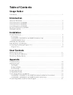
Страница 3: ...ng the L Brackets 6 Side Mount for Your Monitor 7 Connecting the Display Figure 10 1 9 Figure 10 1 10 User Controls Back Panel Controls 11 How to Use the OSD Menus 12 On Screen Display Menus 13 Append...

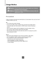
Страница 4: ...mercial cleaners or 50 50 mixture of water and isopropyl alcohol Use a soft cloth moistened with mild detergent to clean the display housing Use only high quality and safety approved AC DC adapter Dis...

Страница 5: ...ual RS 232 Serial USB controller LA1950RTC Capactive touch screen with dual RS 232 Serial USB controller LA1950RTS SAW touch screen with dual RS 232 Serial USB controller LA1950R Pure Glass Non Touch...

Страница 6: ...input Surface Anti glare treatment Interface Dual RS 232 Serial USB controller Transmittance 92 5 Driver Windows 7 VISTA XP 2000 ME 98 NT4 0 CE XP Embedded Linux Apple Mac OS Non Touch Screen for LA19...

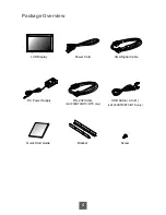
Страница 7: ...4 Package Overview LCD Display Power Cord VGA Signal Cable RS 232 Cable LA1950RTR RTC RTS only USB Cable A to B LA1950RTR RTC RTS only DC Power Supply Quick Start Guide Bracket Screw...

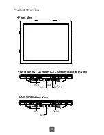
Страница 8: ...Product Overview Front View LA1950RTR LA1950RTC LA1950RTS Bottom View VGA RJ 11 USB RS 232 DC IN LA1950R Bottom View VGA DC IN RJ 11 5...

Страница 9: ...nd bottom sides Bracket Bracket or Bracket Bracket Note You will need a screwdriver to attach the L brackets Your kiosk touch monitor included two L brackets and four screws M4x6 This equipment is int...

Страница 10: ...Side Mount For Your Monitor This monitor can be mounted to the wooden or concrete wall with 4 screws and a pair brackets on the opposites 71 140 26 18 140 342 9 5 75 142 5 7...

Страница 11: ...m thru holes for M4 screws w nuts or no thru holes screws for wood 4mm 2 Sheet metal concealed head threaded studs M4 w nuts LA1950R RTR RTC RTS RECOMMENDED CUSTOMER PANEL CUT OUT 448 9 280 140 376 3...

Страница 12: ...the D SUB connector of your host computer and tighten the screws 10 1 4 Connect the RS 232 or USB cable from the RS 232 or USB port of your display to the RS 232 port 10 1 or USB port 10 1 of your co...

Страница 13: ...Figure 10 1 LA1950RTR LA1950RTC LA1950RTS LA1950R 10...

Страница 14: ...r Enter Down Up Menu OSD Key Menu off status Menu on status Menu appear Menu disappear return to main item Brightness Main item select up Adjust up Contrast Main item select down Adjust down Enter Sel...

Страница 15: ...s still being pressed The Lock Unlock menu will appear for 3 seconds c Use the Enter key to select OSD or Power setting then set at Lock by pushing the UP or Down button d When the UP or Down button i...

Страница 16: ...down Horizontal size The screen image horizontal dot clock adjustment Fine The screen image pixel phase adjustment OSD Left Right Moving OSD menu horizontal position to left or right OSD Up Down Movi...

Страница 17: ...resolution of your computer to make it less than or equal to 1280 x 1024 Problem Image has vertical flickering line bars Use HORIZONTAL SIZE to make an adjustment Check and reconfigure the display mod...

Страница 18: ...mputer graphics card Check all the power switches power cables and VGA signal cable Going to Sleep The LCD display is under the power saving mode In addition the LCD display will enter power saving mo...

Страница 19: ...Product Dimensions 1 00 63 40 100 00 132 50 100 00 432 90 309 50 357 00 360 30 429 60 384 50 75 00 75 00 Front View Back View Side View 16...

Страница 20: ...37 86 72 VESA VGA 640X480 37 50 75 VESA VGA 800X600 35 16 56 VESA VGA 800X600 37 88 60 VESA VGA 800X600 48 08 72 VESA VGA 800X600 46 88 75 Apple Mac 832X624 49 72 75 VESA XGA 1024X768 48 36 60 VESA XG...

Страница 21: ...ore information LA1950RTR LA1950RTC LA1950RTS Optional Calibration Tool Install If you would like to use the Optional Calibration Tool follow the instructions below Please note the calibration tool su...

Страница 22: ...he instructions below Express 1 Power on the computer 2 Make sure that the RS232 or USB cable is connected to the computer 3 Be sure that your EWF is disabled If your EWF is enabled please disable the...

Страница 23: ...nected to the computer 3 Download the driver online and execute 4 Follow the step by step instructions found in the folder file of the driver When changing the Touch Interface RS 232 or USB please fol...

Страница 24: ...itor touch screen or other Planar products visit our online store at www PlanarOnline com or find other stores who carry Planar products at http www planar com howtobuy Technical Support Visit Planar...

Страница 25: ...66 PLANAR1 866 752 6271 or 1 503 748 5799 outside the United States Hours 24 hours a day 7 days a week 2010 Planar Systems Inc 12 10 Planar is a registered trademark of Planar Systems Inc Other brands...

Отзывы: