EL640.480 AG1 Series User’s Manual (020-0350-00B)
15
Connector J2
Standard in AG ET
216.0 [8.50]
208.33 [8.202]
(2 PL)
198.2 [7.80]
192.0 [7.56] Glass
172.7 [6.80] Optional AG Film
165.1 [6.50] Active Area
8.1 [0.32]
17.7 [0.70]
21.6 [0.85]
5.8 [0.23]
7.1
±
1.7
[0.280
±
.067]
149.7 [5.89]
Glass
123.8 [4.88]
Active Area
3.0 [0.12]
132.1 [5.20]
Optional AG Film
128.06
[5.435]
(2 PL)
155.8 [5.13]
Pin 1
Connector J1
128.7 [5.07]
123.3 [4.85]
113.1 [4.45]
85.0 [3.35]
36.3 [1.43]
Optional Right-Angle
Connector
47.7
[1.88]
52.0
[2.05]
54.3
[2.14]
62.7
[2.47]
6.05 [0.238] Typ.
10.29
[0.405]
Typ.
4.5
[0.176]
Typ.
25.0
[0.984]
20.0
[0.787]
Component Envelope
Clearance Envelope
0.25
[0.010]
Optional
AG Film
0.51
[0.020]
Bezel to
Glass
4.3
[0.17]
Ref.
11.4 [0.45]
.3 [.01]
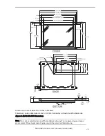
Dimensions in are millimeters; inches in brackets.
Tolerances, unless otherwise stated,
±
0.2 mm. Connector is shown from the back side.
Figure 5. EL640.480 AG1 Dimensions.
Note: This is not a controlled version of the mechanical drawing. Prior to beginning your design,
please contact Planar Applications Engineering for the current detailed drawing.

