background image

ORDER NO.

PIONEER CORPORATION


1-1, Shin-ogura, Saiwai-ku, Kawasaki-shi, Kanagawa 212-0031, Japan

PIONEER ELECTRONICS (USA) INC.

  P.O. Box 1760, Long Beach, CA 90801-1760, U.S.A.

PIONEER EUROPE NV

  Haven 1087, Keetberglaan 1, 9120 Melsele, Belgium

PIONEER ELECTRONICS ASIACENTRE PTE. LTD.

  253 Alexandra Road, #04-01, Singapore 159936

    PIONEER CORPORATION

2010

2010 Printed in Japan

CDJ-350

RRV4069

MULTI PLAYER

CDJ-350

THIS MANUAL IS APPLICABLE TO THE FOLLOWING MODEL(S) AND TYPE(S).

Model

Type

Power Requirement

Remarks

CDJ-350

SYXJ

8

AC 220 to 240 V

CDJ-350

CUXJ

AC 120 V

CDJ-350

FLXJ

AC 110 V to 240 V

CDJ-350

KXJ5

AC 220 V

CDJ-350

AXJ5

AC 220 to 240 VV

For details, refer to "Important Check Points for good servicing". 

K-IZV  MAY

Содержание TRAKTOR PRO CDJ-350

Страница 1: ...SIACENTRE PTE LTD 253 Alexandra Road 04 01 Singapore 159936 PIONEER CORPORATION 2010 2010 Printed in Japan CDJ 350 RRV4069 MULTI PLAYER CDJ 350 THIS MANUAL IS APPLICABLE TO THE FOLLOWING MODEL S AND TYPE S Model Type Power Requirement Remarks CDJ 350 SYXJ8 AC 220 to 240 V CDJ 350 CUXJ AC 120 V CDJ 350 FLXJ AC 110 V to 240 V CDJ 350 KXJ5 AC 220 V CDJ 350 AXJ5 AC 220 to 240 VV For details refer to I...

Страница 2: ...OF THE APPARATUS SHOULD BE DONE BY A SPECIALLY INSTRUCTED PERSON For CD Wave length typ 790 nm Operation output 4 mW CW Class 1 Maximum output Class 1 Under fault condition Laser Pickup specifications and Laser characteristics WARNING This product may contain a chemical known to the State of California to cause cancer or birth defects or other reproductive harm Health Safety Code Section 25249 6 P...

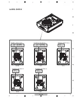
Страница 3: ...3 CDJ 350 5 6 7 8 5 6 7 8 A B C D E F LABEL CHECK Printed on the chassis Printed on the chassis Printed on the chassis Printed on the chassis Printed on the chassis SYXJ8 KXJ5 AXJ5 CUXJ FLXJ ...

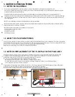
Страница 4: ...he product Please check that neither solder debris nor screws remain inside the product 8 There should be no semi broken wires scratches melting etc on the coating of the power cord Damaged power cords may lead to fire accidents so please be sure that there are no damages If you find a damaged power cord please exchange it with a suitable one 9 There should be no spark traces or similar marks on t...

Страница 5: ... VOLTAGE MONITORING 30 6 SERVICE MODE 31 6 1 TEST MODE 31 6 2 ABOUT THE DEVICE OF CDJ 350 31 6 3 DETAILS ON SERVICE MODE 32 7 DISASSEMBLY 37 8 EACH SETTING AND ADJUSTMENT 45 8 1 NECESSARY ITEMS TO BE NOTED 45 8 2 JOG DIAL ROTATION LOAD ADJUSTMENT 45 8 3 USER SETABLE ITEMS 46 8 4 UPDATING OF THE FIRMWARE 47 9 EXPLODED VIEWS AND PARTS LIST 48 9 1 PACKING SECTION 48 9 2 EXTERIOR SECION 50 9 3 CONTROL...

Страница 6: ...dia GYP1008 0 3 in dia This unit always monitors for power failure and will shut itself off immediately after an error is detected If an error is generated the STANDBY LED will flash after the unit shuts itself off After the unit shuts itself off because of an error unplug the AC power cord and wait 1 minute before turning the unit ON by pressing the STANDBY ON key Repair the unit according to 5 5...

Страница 7: ...ns 220 mm W 107 mm H 288 5 mm D Tolerable operating temperature 5 C to 35 C Tolerable operating humidity 5 to 85 no condensation Analog audio output AUDIO OUT L R Output terminal RCA terminal Output Level 2 0 Vrms 1 kHz Frequency response 4 Hz to 20 kHz S N ratio 115 dB Total harmonic distortion 0 006 USB downstream section USB Port Type A Power supply 5 V 500 mA or less USB upstream section USB P...

Страница 8: ...8 CDJ 350 1 2 3 4 A B C D E F 1 2 3 4 2 2 USABLE DISCS AND USB DEVICES ...

Страница 9: ...9 CDJ 350 5 6 7 8 5 6 7 8 A B C D E F ...

Страница 10: ...10 CDJ 350 1 2 3 4 A B C D E F 1 2 3 4 2 3 PANEL FACILITIES ...

Страница 11: ...11 CDJ 350 5 6 7 8 5 6 7 8 A B C D E F ...

Страница 12: ...he device must be recognized by the PC Check output signals while the JOG dial or TEMPO slider is being operated Audio and operations must be normal Check the appearance of the product No scratches or dirt on its appearance after receiving it for service Item to be checked regarding audio Distortion Noise Volume too low Volume too high Volume fluctuating Sound interrupted See the table below for t...

Страница 13: ...P MACN ASSY DWM2391 2 MAIN ASSY DWX3105 2 CNCT ASSY DWX3111 SMPS ASSY SYXJ8 FLXJ KXJ5 AXJ5 DWR1482 SMPS ASSY CUXJ DWR1481 NSP 1 SLOTIN MECHA ASSY DXA2206 1 TM ASSY S VTM091 DXX2616 Mark No Description Part No Mark No Description Part No LIST OF ASSEMBLIES NOTES Parts marked by NSP are generally unavailable because they are not in our Master Spare Parts List The mark found on some component parts i...

Страница 14: ...D 5 USBB_D_P 6 USBB_D_N 7 GNDD 8 CONT2 9 GNDD 1 0 CONT1 1 1 GNDD 1 2 MUTE_A 1 3 GNDA 1 4 LOUT 1 5 GNDA 1 6 ROUT 1 7 GNDA CN701 VKN1277 A 1 GNDA 2 ROUT 3 GNDA 4 LOUT 5 GNDA 6 MUTE_A 7 GNDD 8 CONT1 9 GNDD 1 0 CONT2 1 1 GNDD 1 2 USBB_D_N 1 3 USBB_D_P 1 4 GNDD JA701 XKB3057 A 3 2 1 4 CN954 DKN1407 A TBB 1 ST1 2 ST1 3 ST1 4 ST1 5 ST2 6 ST2 7 ST2 8 ST2 9 LO 10 LO 11 LO 12 LO 13 GNDS 14 LPS2 15 LPS1 16 G...

Страница 15: ...4 USB_CDETFLG 5 GNDD 6 USB_VBUSON 7 GNDD 8 POWER_ON 9 GNDD 10 VDET 11 GNDD 12 MUTE_PNL 13 GNDD 14 MAIN_RST 15 TSI 16 PNRDY 17 TSO 18 TSCS 19 GNDD 20 TSCK 21 GNDD 22 V 5R6 23 V 5R6 24 V 32 25 GNDD 26 V 5EV 27 GNDD 1 MUTE_1 2 GNDD 3 VBUS_B 4 GNDD 5 USBB_D_P 6 USBB_D_N 7 GNDD 8 CONT2 9 GNDD 1 0 CONT1 1 1 GNDD 1 2 MUTE_A 1 3 GNDA 1 4 LOUT GNDA 4 LOUT 5 GNDA 6 MUTE_A 7 GNDD 8 CONT1 9 GNDD 1 0 CONT2 1 1...

Страница 16: ... SPINDLE MOTOR DXM1197 M STEPPING MOTOR DXM1201 M LOADING MOTOR ASSY S DXX2615 SLOT IN MECHA ASSY DXA2206 IC102 SDRAM 256MB IC101 FLASH 32MB IC103 MAIN CPU IC301 Audio DSP IC201 Servo DSP POWER SUPPLY MAIN SYSTEM BUS 3 3 LPS1 LPS2 LPS2 LO ST1 CN201 CN952 CN954 CN951 ST2 Serial CN401 CN953 CN954 16bit 16bit 16bit IC204 DRIVER SHORT SW TM ASSY S DXX2616 ...

Страница 17: ...05 2 4 CN502 Serial TSI TSO TSCK TSCS POWER_ON MAIN_RST PNRDY IC504 High Side Switch VBUS USB_CDETFLG USB_VBUSON IC103 MAIN CPU 301 o DSP IC107 USB Switch USB Full CN402 CN403 16 7 5 1 3 71 5 4 88 48 70 66 64 75 59 14 4 6 4 6 20 18 20 18 17 15 17 15 16 14 16 14 8 8 Serial IC501 PANEL CPU SLIDER SW LED TEMPO TEMPOR SELECT PUSH RENCO_S RENC_2 RENC_1 95 97 18 20 19 27 26 25 IJO DETECT VDET 10 10 3 4 ...

Страница 18: ... 10 01 1 F FA AL LS SH H Transformer IC402 3 3V REG I IC C3 30 01 1 S 1170B33UC IC403 A AD DS SP P 1 25V D DS SP PC C5 56 63 37 71 1 REG BD00KA5W FP IC302 IC406 D DA AC C 5 0V P PC CM M1 17 74 42 2 REG NJM2872BF05 I IC C3 30 03 3 7 6V O OP PA Am mp p R RN NB B4 45 58 80 0 I IC C5 50 01 1 P PA AN NE EL L C CP PU U M3030RFCPFP P PC C8 85 51 1 J JO OG G S SE ED DS S 7 75 57 73 3 I IC C8 80 01 1 T TC ...

Страница 19: ...r the unit is turned ON Tracking gain adjustment RF gain adjustment If the pickup is reading the program area it will jump to the TOC area The program is downloaded to IC301 audio DSP The Reset signal is sent to the IC103 Pin 158 Audio DSP IC301 Pin 47 receives the Reset signal IC501 Pin 12 receives the Reset signal The Reset signal is sent to the IC502 Panel CPU POWER ON Press the STANDBY ON key ...

Страница 20: ...o be Checked Corrective Action Reference No Cause Diagnostics Point Item to be Checked Corrective Action Reference 10 10 VOLTAGES 9 Basic operation check of CPU DSP 10 11 WAVEFORMS MAIN 7 8 9 STANDBY mode cannot be entered 1 PNLB Assy Check if there is loose connection on the signal line from the PANEL CPU IC501 to the SW S525 If the connection up to the SW is properly made and if the signal is no...

Страница 21: ... TSO signal waveform is not output fixed at either L or H the Main CPU IC103 may be defective Shifting from the STANDBY mode to another mode cannot be performed No Cause Diagnostics Point Item to be Checked Corrective Action Reference No Cause Diagnostics Point Item to be Checked Corrective Action Reference No Cause Diagnostics Point Item to be Checked Corrective Action Reference No Cause Diagnost...

Страница 22: ...B Assy If the symptom persists after the above corrections Check a mounting state of PANEL CPU IC501 If the mounting is OK the PANEL CPU may be defective 3 3 Variable controls not controllable Tempo slider not controllable 1 Loose connection PNLB Assy Check if there is loose connection on the signal line from the PANEL CPU IC501 to the tempo slider VR501 If the connections of signal line are impro...

Страница 23: ...tached remove it The JOG dial turns too freely The load value for the JOG dial is outside the specified range 1 Improper adjust ment or assembly of the JOG dial JOG Assy Check that the load value for the JOG dial is within the specified range referring to Measuring method in 8 2 JOG Dial Rotation Load Adjustment If it is outside the specified range adjust the position of the Cam Plate to change th...

Страница 24: ...age level is abnormal IC406 may be defective If the V 3R3A voltage level is abnormal the IC402 may be defective 2 Loose connections MAIN Assy JACK Assy Check the connection of the audio signal lines ROUT LOUT If connection is improper resolder it 3 Signal errors MAIN Assy Check the AUDIO DSP IC301 If the AUDIO DSP IC301 is OK the DAC IC302 may be defective 9 Basic operation check of CPU DSP 9 Basi...

Страница 25: ...s See 5 3 Diagnosisi of the Pickup Assy for details No loading There is an abnormal noise 1 Improper assembling SLOTIN MECHA Assy Check if the SW lever has shifted on the SWs on the SMLB Assy If the SW lever has shifted on the loading detection SWs S751 S752 correct the position of the SW lever If the soldered SWs are lifted off the board resolder them 2 Signal errors MAIN Assy Check the waveforms...

Страница 26: ...IAGRAM 1 Defective pickup MAIN Assy Check the LD current and measure the resistance value of the actuator Refer to the 5 3 Diagnosis of the Pickup Assy 5 3 Diagnosis of the Pickup Assy 2 Power failure MAIN Assy Check the power voltages V 7R6M V 5R6M VREF1R65 V 3R3S For any power supply section that does not output the voltage check the mounting statuses of the regulator IC and its peripheral parts...

Страница 27: ...ls are OK but the SRVSCLK signal is not output the SERVO DSP IC201 may be defective 10 11 WAVEFORMS MAIN 5 2 9 3 AUDIO DSP IC301 1 MAIN Assy IC301 Check the waveforms and levels of the following signals in PLAY mode Data request DSPDREQ Reset DSPRST must be H Clock Check the waveform of CLK_A_16M If both the Reset and Clock signals are OK but the DSPDREQ signal is not output the AUDIO DSP IC301 ma...

Страница 28: ...e TEMPO button to turn the LD on 5 Measure the voltage difference DC value between the test lands LD3S and LDCHK on the MAIN Assy 6 Press the TEMPO button to turn the LD off Confirm that the voltage difference between test lands LD3S and LDCHK becomes 0 then disconnect the tester 1 Make sure that no CD is loaded 2 Remove the bottom plate and set the LD short circuit switch S951 to Short side see r...

Страница 29: ...iversal Serial Bus controllers USB Composite Device Under Sound video and game controllers USB Audio Device Human Interface Devices HID compliant device USB Human Interface Device A communication check may be easily performed if connection is made with Device Manager displayed on the PC screen 1 USB B connector Whether communication between the PC connected via the USB B connector and this unit is...

Страница 30: ...ANDBY LED will flash after the unit shuts itself off After the unit shuts itself off because of an error unplug the AC power cord and wait 1 minute before turning the unit ON by pressing the STANDBY ON key Diagnostic procedure 1 Unplug the AC power cord 2 Replace R599 on the PNLB Assy with R569 3 Plug the AC power cord 4 Turn the unit ON and check each voltage Unplug the AC power cord after severa...

Страница 31: ...y list An error code and the contents are shown 5 Confirmation of movement of the drive unit It is the mode which checks operation of a mechanism and servo of drive unit 6 Updating firmware Mode for firmware updating Two modes one for updating using a USB memory device and one for updating using a CD ROM are provided Refer to the 8 4 UPDATING OF THE FIRMWARE Device Name Function Part No Ref No Ass...

Страница 32: ...K and TEMPO RANGE keys pressed To enter JOG Load Measurement mode set the TEMPO slider to the MAX position during Service mode For details on how to operate see 2 Confirmation of the button input and an indication function Set the POWER switch to OFF to quit this mode 3 CD drive diagnosis mode To enter CD Drive Diagnosis mode set the POWER switch to ON while pressing the TIME and CD SELECT keys pr...

Страница 33: ... IN OUT OUT ADJUST OUT OUT ADJUST OUT RELOOP EXIT RELOOP EXIT RELOOP TRACK REV o TRACK TRACK FWD p TRACK SEARCH REV m REV SEARCH FWD n FWD JOG MODE VINYL JOG MODE TEMPO TEMPO MASTER TEMPO MASTER TEMPO MASTER TEMPO TIME MODE AUTO CUE TIME ACUE DISPLAY UTILITY DISPLAY BACK All LED lights up All FL lights up EJECT EJECT EJECT BEAT LOOP LOOP DIVIDE LEFT BEAT LOOP LOOP DIVIDE DIVIDE BEAT LOOP LOOP DIVI...

Страница 34: ...decompression error was generated DSP PROGRAM E 8305 Although the filename extension of the music file MP3 AAC WAV AIFF is proper the format of descriptions in the file is not supported Updating error E 8306 Although the piece of music had once been registered in the library database or a playlist etc that piece had been erased from the USB storage device as of time of playback TOC READ ERROR CD C...

Страница 35: ...y a FWD REV direction and do pause Error Rate Count I measure an error rate from a present position doing a play pause for about 10 seconds and display a measurement result in FL Usually a track to measure is made to search and this button is inputted from a pause state For example it is displayed as 3 56E 4 O K etc If an error rate is less than 3 00E 3 it will be displayed as OK If an error rate ...

Страница 36: ...f the OUT LOOP OUT key is pressed while the tracking servo is ON it will be turned OFF TRK ON will be displayed Slide FWD If the SEARCH n FWD key is pressed while the tracking servo is ON it will be turned OFF and the slider will be shifted by about 2 mm in the FWD direction SLD FWD will be displayed Slide REV If the SEARCH m REV key is pressed while the tracking servo is ON it will be turned OFF ...

Страница 37: ...hat 27P FFC does not insert it inward top of MAIN Assy Bottom view Front Rear view Control panel section 27P FFC PNLB Assy MAIN Assy Note on Reassembly PNLB Assy MAIN Assy 27P FFC 27P FFC Note 1 Do NOT look directly into the pickup lens The laser beam may cause eye injury 2 Even if the unit shown in the photos and illustrations in this manual may differ from your product the procedures described h...

Страница 38: ...o SHORT Note After work connect the flexible cable on step 3 then change the position to OPEN 3 Disconnect the two flexible cables and one connector 4 Remove the four screws BPZ30P080FTB 5 Remove the four screws ABZ30P060FTC 6 Remove the MAIN PCB stay 1 MAIN PCB stay 2 1 CNCT Assy 27P FFC 3 4 4 3 4 4 5 5 5 5 Front MAIN PCB stay MAIN PCB stay CN201 CN401 CN402 6 3 CN403 ...

Страница 39: ...e 05 Assy 3 Remove the SLOTIN MECHA section 2 SLOTIN MECHA Section 2 1 2 1 2 1 2 2 1 1 Float spring G5 SLOTIN MECHA section Float spring G5 Float base 05 Assy Float base 05 Assy 3 Damper Direction of the dampers when attaching them When attaching the dampers place them so that their projections large face front Projection large to the front ...

Страница 40: ...late 1 Mecha Plate 1 Disconnect the flexible cable 2 Unhook the four hooks 2 SLOTIN MECHA Assy 2 1 1 3 Mecha plate SLOTIN MECHA Assy Mecha plate CN751 1 2 2 2 2 This boss is not installation position Earth spring Note of earth spring Be sure not to lose it Be careful to the installation places Confirm it by viewing ...

Страница 41: ...iew Binder Rear side 3 When binding the cables from the SLMB Assy be careful that the bound part will not protrude from the edge of the board toward the rear Bind them so that the bound part will come to the upper side of Side A Note on Reassembly SLMB Assy Side A Side B Side A Side B Bound part Cable OK NG NG ...

Страница 42: ... following cleaning materials Cleaning liquid GEM1004 Cleaning paper GED 008 2 Unhook the four hooks 3 Release the flexible cables as required 4 Remove the TM Assy S VTM091 Pickup lens TM Assy S VTM091 TM Assy S VTM091 2 2 2 2 4 Rear view 1 Pickup 1 Short circuit two positions of figure solodering short Note After working connect the flexible cable then remove the soldered joint open 3 TM Assy S V...

Страница 43: ...8 5 6 7 8 A B C D E F Arrangement of the FFC Pickup FFC Spindle motor FFC Stepping motor FFC 5P FFC CNCT Assy 5P FFC SLMB Assy CNCT Assy CNCT Assy CNCT Assy Stepping motor Stepping motor FFC Spindle motor FFC Pickup FFC ...

Страница 44: ...g JOG dial section to front side JOG dial section CN504 CN501 2 2 3 2 2 1 1 A B 1 4 3 2 JOG dial rotation load adjustment mechanism JOG Dial Rotation Load Adjustment Mechanism Screw tightening order About details of Adjustment etc refer to the 8 2 JOG DIAL ROTATION LOAD ADJUSTMENT The other screws are random order Bottom view Front Bottom view Front ...

Страница 45: ...rsion Perform the each item when the following parts are replaced MAIN Assy Flash ROM Confirmation of the version of the firmware MAIN DSP Updating to the latest version of the firmware Part of JOG dial section JOG dial rotation load adjustment JOG Check Mode ON JOG Check Mode CANCEL POWER OFF Mode for checking the load on the Jog dial It is the mode which judges the load light heavy numerically w...

Страница 46: ...uct 80 25 msec 5 If the rotation decreasing time is not in the spec change the adjustment value of the Cam plate and do the above inspection from No 3 to No 4 again To increase the load To decrease the load Adjust to 0 Cam plate Fig 1 Cam plate Fig 2 Example of displaying FL Judgement Average of rotation decreasing time If it is outside the specified range 1 2 3 1 2 adjust the position of the Cam ...

Страница 47: ...e message of COMPLETE will be displayed if update is completed please return on a power supply 1 A file to update is copied to CD R RW 2 Please turn on a power supply pushing both the buttons of SOURCE SELECT DISC and RELOOP Please continue pushing until DOWNLOAD screen appears 3 The rest is the same as that of the case where USB memory is used When the power supply has been turned off on the way ...

Страница 48: ...e component parts indicates the importance of the safety factor of the part Therefore when replacing be sure to use parts of identical designation Screws adjacent to b mark on product are used for disassembly For the applying amount of lubricants or glue follow the instructions in this manual In the case of no amount instructions apply as you think it appropriate or or or or SYXJ8 only KXJ5 only F...

Страница 49: ...aution Card SB See Contrast table 2 NSP 24 License Key Label Assy DXA2190 Mark No Description Part No Mark No Symbol and Description CDJ 350 SYXJ8 CDJ 350 CUXJ CDJ 350 FLXJ CDJ 350 KXJ5 CDJ 350 AXJ5 1 Power Cable ADG1154 ADG7022 ADG1154 XDG3054 ADG7079 2 Power Cord Taiwan Not used Not used ADG7097 Not used Not used 7 Operating Instructions En Fr De DRB1508 Not used Not used Not used Not used 8 Ope...

Страница 50: ... 2 3 4 A B C D E F 1 2 3 4 9 2 EXTERIOR SECION A A B B C D E E F D C D H A C F CONTACT SIDE NON CONTACT SIDE Spindle Motor Pickup Assy SLMB CN751 Refer to 9 3 CONTROL PANEL SECTION Refer to 9 4 SLOTIN MECHA SECTION ...

Страница 51: ...ead wire DE007VE0 9 Damper CNV6011 10 Earth Spring DBH1398 11 Float Spring G5 DBH1494 12 Mecha Plate DNH2642 13 Main PCB Stay DNH2914 14 Rear Chassis DNH2915 NSP 15 Chassis See Contrast table 2 16 Rubber Foot VEB1349 NSP 17 P U Caution Label DRW2448 18 19 20 Screw M3 x 5 DBA1340 21 Screw ABZ30P060FTC 22 Screw BBZ30P060FTB 23 Screw BPZ30P080FTB 24 Screw PPZ30P080FTB Mark No Symbol and Description C...

Страница 52: ...N402 Note During reassembly be careful not to scratch the sliding surface of the back side of the Jog dial B Scratches on the sliding surface may cause noise during turning of the Jog dial Lubricating oil GYA1001 Lubricating oil GYA1001 CONTACT SIDE NON CONTACT SIDE Arm spring Hook Hook Encoder arm ...

Страница 53: ...e DEC2889 20 Lever Cushion A DEC3001 21 Lever Cushion B DEC3002 22 Slide Sheet DEC3227 23 Ground Holder DNH2917 24 Jog Lever DNK4763 25 Jog Shaft DNK4934 26 Encorder Arm DNK4936 27 Encorder Gear DNK4937 28 Load Gear DNK5178 29 Lever Holder DNK5206 30 Shaft Holder DNK5514 31 Cam Plate DNK5546 32 Push Plate DNK5547 33 Beat Loop Lens DNK5548 34 Control Panel DNK5549 35 Color Ring A DNK5550 36 Jog Hol...

Страница 54: ...CN955 CNCT CN951 Lubricating oil GYA1001 Cleaning liquid GEM1004 Cleaning paper GED 008 Dyfree GEM1036 Dyfree GEM1036 Dyfree GEM1036 Dyfree GEM1036 Lubricating oil GYA1001 Lubricating oil GYA1001 B CONTACT SIDE NON CONTACT SIDE Note The TM Assy S VTM091 is supplied only in assembly form not as a single parts ...

Страница 55: ...75 13 SW Lever Spacer SV DEC2831 14 Loading Lever DNK3406 15 Main Cam DNK3407 16 Disc Guide DNK3478 17 Clamp Arm DNK3576 18 Eject Lever DNK3684 19 Lever AP DNK3835 20 Lever BP DNK3836 21 Loading Gear DNK3911 22 Drive Gear DNK3912 23 Loading Base SV DNK4369 24 SW Lever SV1 DNK4370 25 SW Lever SV2 DNK4371 26 Gear Holder SV DNK4372 27 Clamper Assy S DXX2661 28 29 30 Screw BPZ20P060FTC 31 Spacer POR T...

Страница 56: ... 16 SW1_DVD CD 17 C 18 D 19 E 20 Vcc 21 VREF 22 F 23 GNDS 24 CKSSYB K F is No Mount STBY SR NM Notes CKSRYB K F RS1 16SS J CEHVQW M F RS1 10SR J SR LPS2 LO LPS1 LO CN751 VKN1265 A LPS2 1 LPS1 2 GNDS 3 LO 4 LO 5 GNDD DSG1017 A S752 1 2 DSG1017 A S751 1 2 Slot in Mecha SW LO LO ZWNN1007G28 8 06A L 60mm GRAY ZWNN1007G28 9 06A L 60mm WHITE A B B SLMB ASSY DWX3108 LOADING MOTOR ASSY S DXX2615 SPINDLE M...

Страница 57: ...951 0 1u C964 0 01u C955 0 1u C968 0 01u C966 NM C967 NM C965 NM GNDD GNDS L952 CTF1410 A L951 CTF1410 A R951 0 S951 VSH1018 A 1 2 3 V 5M V 5P R967 0 SR R968 0 SR 2 2 u 1 6 C 9 6 9 C970 NM SR DKN1407 A CN954 1 ST1 2 ST1 3 ST1 4 ST1 5 ST2 6 ST2 7 ST2 8 ST2 9 LO 10 LO 11 LO 12 LO 13 GNDS 14 LPS2 15 LPS1 16 GNDS 17 GNDS 18 GNDS 19 V 5P 20 F 21 VREF 22 E 23 D 24 C 25 B 26 A 27 VR780PD 28 GNDS 29 LD780...

Страница 58: ... 164 PF4 FWE LCD_DATA4 SSCK1 165 PF3 TCLKD LCD_DATA3 SCS0 166 PF2 TCLKC LCD_DATA2 SSO0 167 PF1 TCLKB LCD_DATA1 SSI0 168 VCC10 169 PF0 TCLKA LCD_DATA0 SSCK0 170 VSS10 171 PVSS14 172 TMS 173 PVCC13 174 TDI 175 ASEBRKAK ASEBRK 176 TRST 177 TDO 178 TCK 179 PB0 SCL0 PINT0 IRQ0 180 PB1 SDA0 PINT1 IRQ1 181 PB2 SCL1 PINT2 IRQ2 181 182 PB3 SDA1 PINT3 IRQ3 182 183 PVCC14 183 184 PVCC15 184 185 PB4 SCL2 PINT...

Страница 59: ...D _ F L M 1 3 9 P F 2 1 S S I S C K 1 L C D _ C L K 1 4 0 V C C 8 1 4 1 P F 2 2 S S I W S 1 L C D _ V C P W C A U D A T A 2 1 4 2 V S S 8 1 4 3 P V S S 1 2 1 4 4 145 PF23 SSIDATA1 LCD_VEPWC AUDATA3 146 PVCC11 147 PF17 FCE LCD_CL1 148 PF16 FRB LCD_DON 149 PF15 NAF7 LCD_DATA15 SD_CD 150 PF14 NAF6 LCD_DATA14 SD_WP 151 PF13 NAF5 LCD_DATA13 SD_D1 152 PF12 NAF4 LCD_DATA12 SD_D0 153 PF11 NAF3 LCD_DATA11 ...

Страница 60: ... E 8 9 R S T 9 0 V D D 5 9 1 I O 0 B E M P H I 9 2 I O 1 B B C K I 9 3 I O 2 B A I N 9 4 I O 3 B L R C K 9 5 E M P H 9 6 B C K 9 7 A O U T 9 8 L R C K 9 9 DOUT 1 0 0 100 2SA1036K PQR Q201 R 2 4 1 2 2 k R 2 3 2 2 2 R 2 4 4 2 2 k R 2 3 3 2 2 R226 15k R 2 4 2 2 2 k R 2 4 0 2 2 k R235 22k R 2 3 7 3 3 R 2 3 8 3 3 R230 5 6k R285 NM R284 NM R283 NM R282 NM R281 NM R280 NM R279 NM R278 NM R277 NM R225 150...

Страница 61: ... 7R6M V 3R3B VREF1R65 VREF1R65 VREF1R65 VREF1R65 V 3R3S V 5R6M VREF1R65 V 3R3 V 7R6M CLK_S_16M 1 13C CPU_SRV 1 13J V 5R6 47u 16 C246 47u 16 C247 4 7 u 1 6 C 2 5 2 4 7 u 6 3 C 2 3 9 C 2 6 7 V C G 1 0 6 3 A C233 0 1u C238 0 033u C 2 7 8 S Q 2 2 u C244 0 1u C 2 5 4 1 0 0 p S C H C 2 7 2 S C H 3 3 0 p C253 0 1u C 2 8 6 N M S R C 2 7 7 N M S R C 2 5 9 0 1 u C248 470p SCH C 2 4 5 0 1 u C 2 7 1 S C H 1 0...

Страница 62: ... P _ V D D 4 1 P L L P _ G N D 4 2 P L L D _ G N D 4 3 P L L D _ V D D 4 4 E X T A L 4 5 P I N I T _ N M I 4 6 R E S E T _ B 4 7 M O D D _ I R Q D 4 8 M O D C _ I R Q C 4 9 M O D B _ I R Q B 5 0 M O D A _ I R Q A 5 1 C O R E _ V D D _ 3 5 2 C O R E _ G N D _ 3 5 3 S D O 0 _ P E 1 1 5 4 S D O 1 _ P E 1 0 5 5 S D O 2 _ S D I 3 _ P E 5 6 S D O 3 _ S D I 2 _ P E 5 7 S D O 4 _ S D I 1 _ P E 5 8 S D O 5...

Страница 63: ... R R328 2 2k D R325 220 D R334 5 1k D R331 3 3k D R 3 2 4 4 7 k D R348 NM SR R 3 3 8 2 2 k R349 22k R326 220 D R 3 2 2 1 0 k V AUDIO V 5A V 5EV V 7R6A V 3R3 V AUDIO V 5A V 3R3A V 7R6A MUTE_PNL 4 11C CPU_AUDIO 1 12B MUTE_CAP 4 11F MUTE_A 4 11E ROUT 4 11E LOUT 4 11E 4 7 u 1 6 C 3 3 3 N M C 3 3 4 100u 6 3 C322 2 2 u 6 3 C 3 1 5 1 0 0 u 6 3 C 3 2 0 4 7 u 1 6 C 3 3 1 100u 6 3 C323 4 7 u 6 3 C 3 1 8 C 3...

Страница 64: ...2 2 k F R 4 2 2 3 3 k F R491 NM R 4 9 2 N M R 4 9 4 1 0 0 k R 4 9 5 2 2 0 R 4 0 5 0 R 4 0 6 N M R 0 R 4 0 8 N M R 4 0 9 N M R 4 2 7 5 6 k F R431 10k R 4 4 4 1 0 0 R425 NM R 4 4 1 1 0 k R 4 1 6 N M R 4 3 6 1 0 k R 4 4 0 2 2 k R448 10k R 4 2 6 3 3 k F R412 NM R 4 6 3 1 k R420 NM R 4 2 9 1 0 k R 4 1 0 4 7 k R 4 4 6 1 0 k R 4 1 1 1 0 k R 4 0 7 0 R 4 3 4 1 0 0 R 4 3 2 1 0 0 R 4 5 3 1 0 0 R437 NM R 4 1 ...

Страница 65: ...P32 V 5R6 V 5EV V 7R6M V 3R3 V 5IJO VDET 6E USB_VBUSON 1 13G TSO 1 13I LOUT 3 12C MUTE_A 3 12F ROUT 3 12D PNRDY 1 13H POWER_ON 11C 2F MUTE_CAP 3 12F USBA_D_P 1 16F CONT1 1 11A USBB_D_P 1 16F USBA_D_N 1 16G USBB_D_N 1 16G MAIN_RST 1 15J VBUS_B 1 16D POWER_ON 2F 8B TSCK 1 10K TSCS 1 13H USB_CDETFLG 1 13H TSI 1 13I MUTE_PNL 3 9F CONT2 1 11A R1010 0 R1011 0 4 7 u 1 6 C 4 5 2 47u 16 C431 4 7 u 1 6 C 4 ...

Страница 66: ...D 16 MUTE_1 17 100u C70 NP 100u C70 NP D709 RKZ5 6KG B2 GNDA GNDD VA701 NM 470u 16 C707 AT C714 NM CH C715 NM CH C712 NM CH RS1 10SR J CCSRCH J F CEANP M F NM AT CEAT M F CKSRYB K F NP is No Mount CH Notes D JACK ASSY DWX3107 C 4 4 CN403 Analog Audio Signal Route USB_D_N Signal Route USB_DN USB_D_P Signal Route USB_DP USB_DN USB_DP CONTROL1 Signal Route CONT1 CONTROL2 Signal Route CONT2 CONT1 CONT...

Страница 67: ...1237 A JA703 V 5DETD 1 USBB_N 2 USBB_P 3 GNDD 4 RT1 RT2 L701 NM 1 2 3 4 R712 1k R708 0 R704 1k R707 0 R702 47k R701 47k R706 150 R715 270 R713 150 R711 1k 100 R709 R710 150 R705 150 R714 470 R703 1k D707 NNCD6 2MF C706 NM C703 1u 10 C708 NM CH C709 NM CH C704 1000p CH C711 CH 1000p C705 1000p CH C710 1000p CH D702 1SS352 D701 1SS352 Q703 INC2002AC1 Q702 INC2002AC1 Q701 INC2002AC1 Q704 INC2002AC1 U...

Страница 68: ...5 CS1 49 P4_4 CS0 50 P4_3 A19 51 P4_2 A18 52 P4_1 A17 53 P4_0 A16 54 P3_7 A15 55 P3_6 A14 56 P3_5 A13 57 P3_4 A12 58 P3_3 A11 59 P3_2 A10 60 P3_1 A9 61 VCC2 62 P3_0 A8 63 VSS2 64 P2_7 A7 65 P2_6 A6 66 P2_5 A5 67 P2_4 A4 68 P2_3 A3 69 P2_2 A2 70 P2_1 A1 71 P2_0 A0 72 P1_7 D15 73 P1_6 D14 INT4 74 P1_5 D13 INT3 75 P1_4 D12 76 P1_3 D11 77 P1_2 D10 78 P1_1 D9 79 P1_0 D8 80 P0_7 AN0_7 D7 81 P0_6 AN0_6 D...

Страница 69: ...R624 NM R646 NM SA R620 10 R634 1 8 SQ R628 2 7 R633 1 8 SQ R565 10k R642 NM R591 270 R586 1 5k R592 360 R585 2 7k R639 220 R561 10k R552 4 7k R567 10k R507 100 R559 10k R622 NM R593 220 R609 0 R640 220 NM R616 1k F R584 390 R550 47k R576 1k R618 10 R617 2 7k F R560 10k R641 680 R623 NM R649 NM SA R619 10 R630 2 7 R562 10k R590 270 R597 360 R647 NM SA R548 NM R506 220 DCH1324 A C547 SLI 343Y8C KLM...

Страница 70: ...K 3 E 4 V 5 R803 100k R802 4 7k R805 390 R806 330 R804 22k R801 NM C801 0 1u C802 NM D801 1SS352 Q801 LSC4081UB QR RS1 10SR J CKSRYB K F NOTES is No Mount NM DKP3864 A CN851 GNDD 1 V 5 2 JOG1 3 JOG2 4 GNDD PC851 SEDS 7573 VLED 5 GND 4 B 3 GND1 6 A 1 VCC 2 V 5 V 5 R851 0 R852 330 C853 0 01u C852 0 01u C851 2 2u SQ Board in Connector RS1 10SR J CKSRYB K F NOTES SQ CKSQYB K F E CN504 E CN501 ...

Страница 71: ...71 CDJ 350 5 6 7 8 5 6 7 8 A B C D E F ...

Страница 72: ...UTION FOR CONTINUED PROTECTION AGAINST RISK OF FIRE REPLACE WITH SAME TYPE AND RATINGS OF FUSE AC POWER CORD FOR SYXJ8 FLXJ KXJ5 and AXJ5 The mark found on some component parts indicates the importance of the safety factor of the part Therefore when replacing be sure to use parts of identical designation ...

Страница 73: ...73 CDJ 350 5 6 7 8 5 6 7 8 A B C D E F H C 4 4 CN401 ...

Страница 74: ...ED PROTECTION AGAINST RISK OF FIRE REPLACE WITH SAME TYPE AND RATINGS OF FUSE The mark found on some component parts indicates the importance of the safety factor of the part Therefore when replacing be sure to use parts of identical designation AC POWER CORD FOR CUXJ H SMPS ASSY DWR1481 ...

Страница 75: ...75 CDJ 350 5 6 7 8 5 6 7 8 A B C D E F H C 4 4 CN401 ...

Страница 76: ...sy AUDIO MUTE OFF Checking the voltage levels inside the various Assys It is assumed that the SMPS Assy output level is normal Name Point to be checked Normal voltage level Possible defective part V 5R6 5 53 to 5 87 V IC409 V 3R3 3 2 to 3 4 V IC401 V 1R2 1 19 to 1 21 V IC404 R426 R427 V 3R3A 3 27 to 3 33 V IC402 V 1R25 1 24 to 1 26 V IC403 R421 R422 V 5R6M 5 54 to 5 66 V IC206 V 3R3S 3 27 to 3 33 ...

Страница 77: ... 11 IC103 pin 135 LPS1 V 1 0 V div H 1 S div DISC EJECT 3 IC201 pin 73 CLK_S_16M V 1 0 V div H 100 nS div 8 Foot of R191 TSCK V 1 0 V div H 1 μS div 12 IC103 pin 134 LPS2 V 1 0 V div H 1 S div DISC IN 4 IC103 pin 85 SH_STATUS_TP V 1 0 V div H 500 mS div 9 Foot of R163 TSI V 1 0 V div H 50 μS div 12 IC103 pin 134 LPS2 V 1 0 V div H 1 S div DISC EJECT 5 IC103 pin 72 DSPDREQ V 1 0 V div H 20 μS div P...

Страница 78: ... pin 3 JOG1_C V 1 0 V div H 10 mS div JOG scratch 2 V501 pin 35 FLBK V 1 0 V div H 100 μS div 4 V501 pin 32 FLSO V 1 0 V div H 100 μS div 6 CN501 pin 4 JOG2_C V 1 0 V div H 10 mS div JOG scratch E PNLB ASSY NOTE The following waveforms were measured at the point of the corresponding balloon number in the schematic diagram and PCB diagram ...

Страница 79: ...79 CDJ 350 5 6 7 8 5 6 7 8 A B C D E F ...

Страница 80: ...969 A30C5 G 1 5 10 1 5 10 15 20 1 5 1 1 5 10 15 20 25 30 35 40 45 50 1 1 LPS2 2 LPS1 3 GNDD 4 LO 5 LO SLOTSW SLOTSW SLMB DWX3108 5 1 CONTACT SIDE UP S751 CN751 S752 C7 G 1 1 5 1 STEPPING MOTOR PICKUP ASSY SPINDLE MOTOR CN955 C CN201 CN954 CN951 CN952 CN953 CN751 NOTE FOR PCB DIAGRAMS 1 The parts mounted on this PCB include all necessary parts for several destinations For further information for re...

Страница 81: ...DE B A CNCT ASSY B SLMB ASSY DNP2560 B DNP2561 B CNCT DWX3111 C966 C967 C965 C968 C953 C952 C955 C970 R968 R967 L951 LF 1 LPS2 2 LPS1 3 GNDD 4 LO 5 LO SLOTSW SLOTSW SLMB DWX3108 LO LO 1 5 WHITE GRAY ADD SOLDER CN751 LF CN955 CN954 CN951 CN952 CN953 CN751 ...

Страница 82: ...408 R448 R440 R443 R266 C471 R336 R339 R340 R344 Q405 R429 R418 R420 R417 R431 R434 R405 R406 R419 R428 R430 C463 R185 R186 R187 KN401 KN403 KN402 R354 C482 C487 R496 R482 R473 R477 R498 C318 CN403 R499 C494 D101 D303 D304 C316 C467 R470 C472 R483 C470 C473 C340 C341 C188 R1003 R1004 R1005 R1006 R1007 R1008 C193 R345 C342 C196 C402 C1002 C1004 R1010 R1011 R359 C334 C405 C406 C320 C322 C323 C431 C3...

Страница 83: ...171 R172 C137 R173 C138 C139 C142 C143 C144 C145 C146 C148 C149 C150 C151 C152 C153 C154 C155 C156 C157 C158 C159 C160 C161 C162 C163 C164 C165 C166 C167 C168 C169 C171 C173 60 120 180 240 IC103 IC104 L401 R201 C177 C178 R109 C179 R266 14 7 IC105 C170 C180 C182 C479 C480 R177 R178 R179 R274 R184 R185 R186 R187 KN404 R276 C202 C225 L201 L202 L203 L204 R277 R278 R279 X101 C260 C495 C261 C186 IC404 C...

Страница 84: ...153 R155 R156 R159 R160 R161 R167 R175 Q201 24 48 IC101 27 54 IC102 IC107 R208 R209 IC408 C422 C135 C140 C141 C136 C462 C176 Q109 Q104 Q107 C476 C181 C477 C478 C242 C243 R253 R254 R257 R259 R409 R413 C419 C415 R188 R183 R182 R181 R180 R197 R198 C465 R275 R280 R189 R190 R285 C183 R163 R162 C185 R191 C184 R192 R193 KN102 C147 R282 R284 R283 L218 L205 L206 L209 L212 L208 L207 L210 L211 L213 L217 L215...

Страница 85: ...483 R480 R481 C490 C488 C489 R476 R478 R475 R479 R350 R349 C339 C324 C325 C326 C327 C328 C329 C491 C492 C493 L405 R323 R324 R325 R326 R327 R328 R329 R330 R331 R332 R333 R334 D402 D403 D404 D405 C468 C499 C498 C497 C496 C469 R356 R357 D406 C474 C437 R351 C187 C189 C190 R1009 R1002 R1001 C343 C461 C1003 C1001 C1005 C1006 R1101 R358 C1007 1 E 1 1 1 1 1 1 1 1 1 10 5 1 5 10 15 20 25 30 35 40 45 50 55 6...

Страница 86: ...9 S501 S502 S503 D506 S504 D507 S505 D508 D509 S510 D510 S511 D511 C513 D512 D514 S518 D515 S519 D516 S520 D517 S521 S522 S523 S524 J603 J586 J619 S527 V501 J585 S512 S513 S514 S515 J594 J607 J623 J545 J513 J593 J536 J614 J590 J521 J538 J543 J621 J526 J537 J622 J503 J551 J518 J560 J583 J618 J563 J564 J597 J611 J530 J596 J587 J569 J577 J624 J588 J510 J541 J535 J610 J574 J533 J571 J515 J514 J558 J50...

Страница 87: ...X3106 DWX GNDD VR501 C501 508 C504 D504 D505 C507 C511 C513 S516 S517 7 C505 J589 J512 J520 CN504 J567 J545 J611 J541 C7 G JP501 JP502 J559 J531 J519 J598 J581 J620 CN501 CN502 J612 J557 J511 J509 1 1 1 1 5 10 15 20 25 1 GNDD 2 TCH 3 V 5 1 2 3 4 TCHB DWX3109 1 3 C7 G CN801 IC801 1 1 JOGB DWX3124 1 GNDD 4 J851 PC851 CN851 C7 G 1 5 1 VR501 DNP2561 B DNP2561 B DNP2561 B CN851 C CN402 CN502 CN801 CN50...

Страница 88: ... PNLB DWX3106 ADD SOLDER ADD SOLDER GNDD V 5R6 V 32 V 5R6 V 32 V 5R GNDD V 5EV GNDD V 5SW GNDD GNDD R584 R501 R504 C508 R559 C509 R502 C502 R585 C510 R513 C506 R558 R514 R503 Q503 Q504 C503 R509 R505 R603 R601 R600 R604 R605 R627 C560 C561 C572 R646 R648 R649 R650 D501 D524 C512 A B C 0 1 2 3 0 1 2 3 4 5 6 7 8 9 1 1 0 0 BEND BEND LF E E 1 V 5 2 TCH 3 GNDD 1 2 3 4 DWX3109 TCHB 1 3 R801 R802 R803 R8...

Страница 89: ...3 Q507 Q502 Q515 Q508 Q510 IC502 C544 C530 C529 C546 3 0 5 0 8 0 1 0 0 IC501 R544 R545 R509 R505 IC504 R603 R601 R600 R602 R599 R604 R598 IC505 C548 R606 IC506 C550 R608 R609 R531 R532 R612 L505 R613 R615 R624 R618 R620 R625 C552 R621 R614 R622 R616 R619 Q517 R623 R617 C554 R626 R634 R631 R630 R633 R628 R582 R629 R632 R636 R635 R607 R583 R637 R638 R639 R640 R610 R568 R569 L501 L502 L504 L503 R641 ...

Страница 90: ...90 CDJ 350 1 2 3 4 A B C D E F 1 2 3 4 11 4 SMPS ASSY H H SMPS ASSY SIDE A SIDE A AC POWER CORD CN1 C CN401 CN2 FOR SYXJ8 FLXJ KXJ5 and AXJ5 ...

Страница 91: ...91 CDJ 350 5 6 7 8 5 6 7 8 A B C D E F H H SMPS ASSY SIDE B SIDE B CN1 CN2 FOR SYXJ8 FLXJ KXJ5 and AXJ5 ...

Страница 92: ...92 CDJ 350 1 2 3 4 A B C D E F 1 2 3 4 H H SMPS ASSY SIDE A SIDE A AC POWER CORD CN1 C CN401 CN2 FOR CUXJ ...

Страница 93: ...93 CDJ 350 5 6 7 8 5 6 7 8 A B C D E F H H SMPS ASSY SIDE B SIDE B CN1 CN2 FOR CUXJ ...

Страница 94: ... DWX3111 1 SMPS ASSY SYXJ8 FLXJ KXJ5 AXJ5 DWR1482 1 SMPS ASSY CUXJ DWR1481 Mark No Description Part No A CNCT ASSY MISCELLANEOUS L 951 952 INDUCTOR CTF1410 S 951 SLIDE SWITCH VSH1018 CN951 12P FFC CONNECTOR DKN1450 CN952 24P FFC CONNECTOR DKN1445 CN953 5P CONNECTOR DKN1402 CN954 CONNECTOR DKN1407 CN955 4P CONNECTOR DKN1288 RESISTORS R 967 968 RS1 10SR0R0J Other Resistors RS1 16SS J CAPACITORS C 95...

Страница 95: ...179 VCG1063 C 162 164 170 174 CKSSYB104K10 C 166 266 284 469 CKSRYB103K50 Mark No Description Part No C 171 173 CCSRCH180J50 C 176 178 272 274 CCSSCH331J50 C 180 187 193 211 VCG1063 C 184 254 271 486 CCSSCH101J50 C 185 CCSSCH150J50 C 194 210 231 235 CKSSYB103K16 C 201 204 209 212 CKSSYB104K10 C 202 225 239 318 CEHVAW470M6R3 C 203 CCSSCH470J50 C 205 220 CKSSYB153K16 C 206 207 CKSSYB223K16 C 208 CKS...

Страница 96: ... USB A CONNECTOR DKN1620 V 501 VFD DEL1072 VR501 VR DCV1009 S 501 511 525 SWITCH VSG1024 Mark No Description Part No S 512 515 518 524 TACT SWITCH DSG1079 S 516 517 TACT SWITCH DSG1117 S 527 ROTARY SW YSD5019 X 501 CRYSTAL RESONATOR 15 975 MHz DSS1166 CN501 L PLUG 4P KM200NA4L CN502 27P CONNECTOR VKN1287 CN504 L PLUG 3P KM200NA3L 0 LED SPACER DEC3335 RESISTORS R 513 514 RS1 10SR2201F R 616 RS1 10S...

Страница 97: ...Y MISCELLANEOUS CN851 CONNECTOR ASSY 4P DKP3864 RESISTORS All Resistors RS1 10SR J MISCELLANEOUS PC 851 PHOTO INTERRUPTER SEDS 7573 CAPACITORS C 851 CKSQYB225K10 C 852 853 CKSRYB103K50 H SMPS ASSY There is no service parts Mark No Description Part No ...

Отзывы: